
Aurora in the Northeast US
Some notes on how I photographed the aurora borealis in the northeast US in 2024 and 2025.
In recent years, the northern lights have been seen in locations further south than ever before. My first time seeing the aurora was 10/10/2024. I was in Tappan Zee New York. The second time was only a year later, 11/12/2025. This time I was at Hopewell Lake in Pennsylvania. The aurora in 2024 was stronger than the one in 2025, at least from my locations.
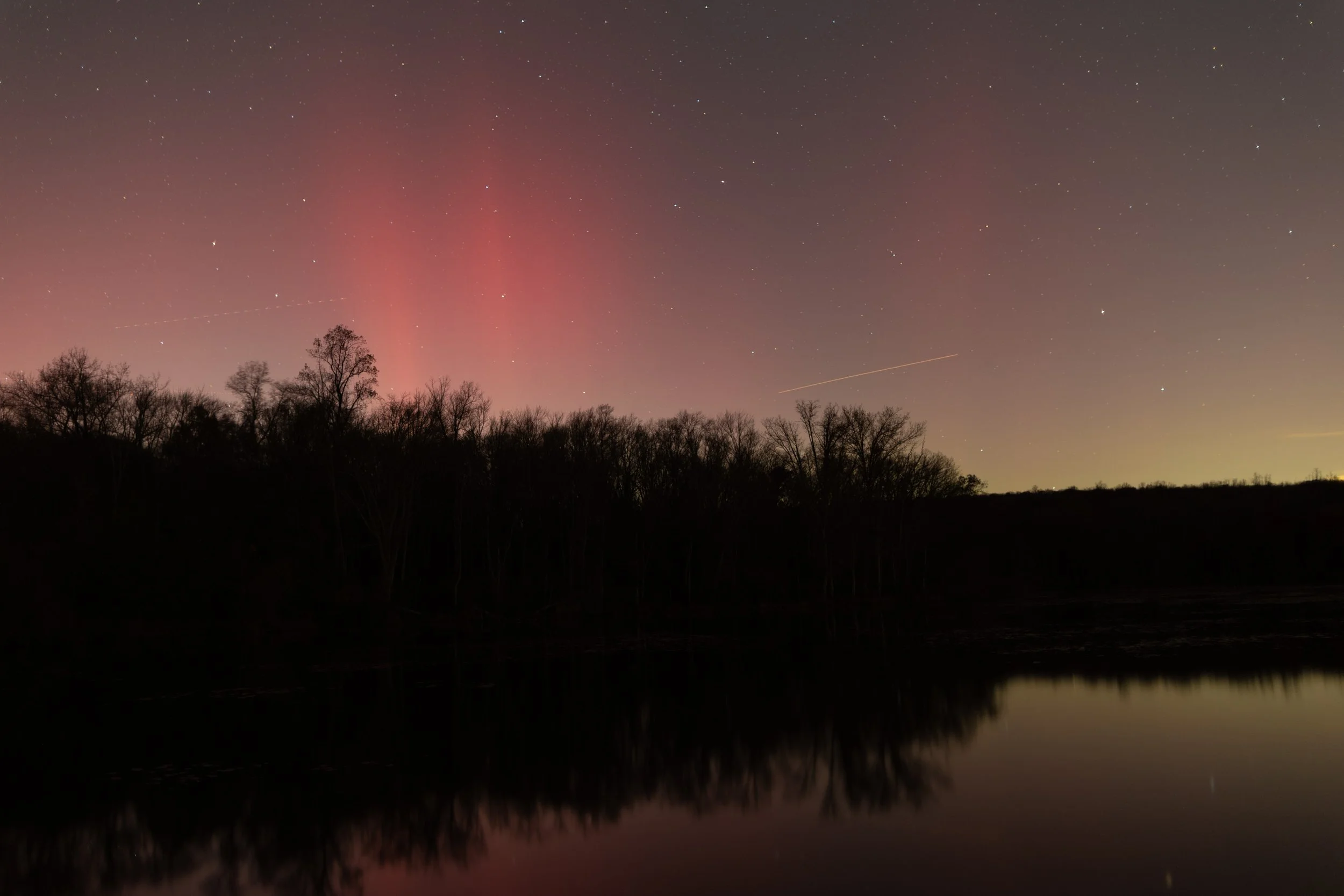
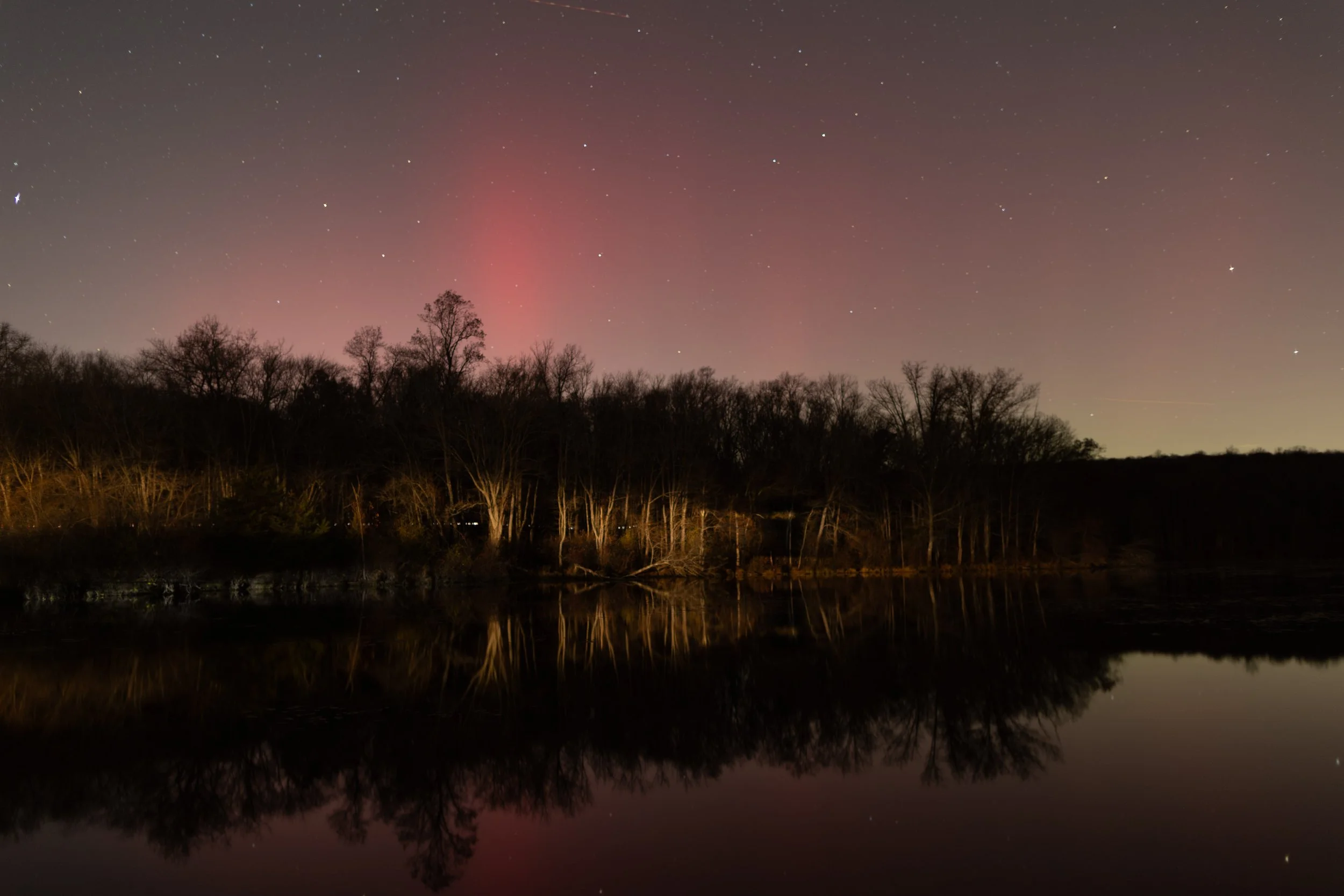
Aurora from Hopewell Lake, November 2025. F/1.4, 30 sec, ISO 100
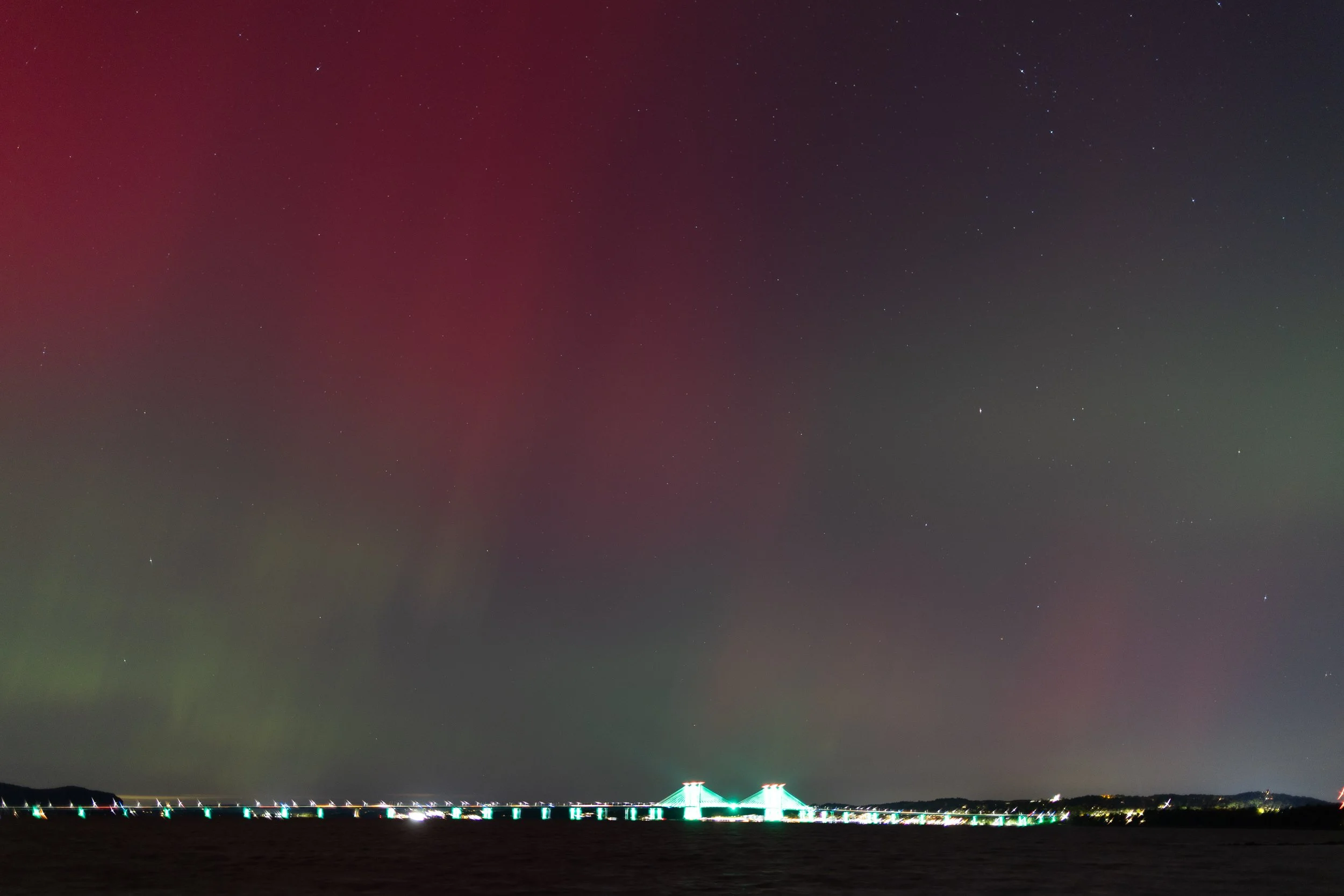
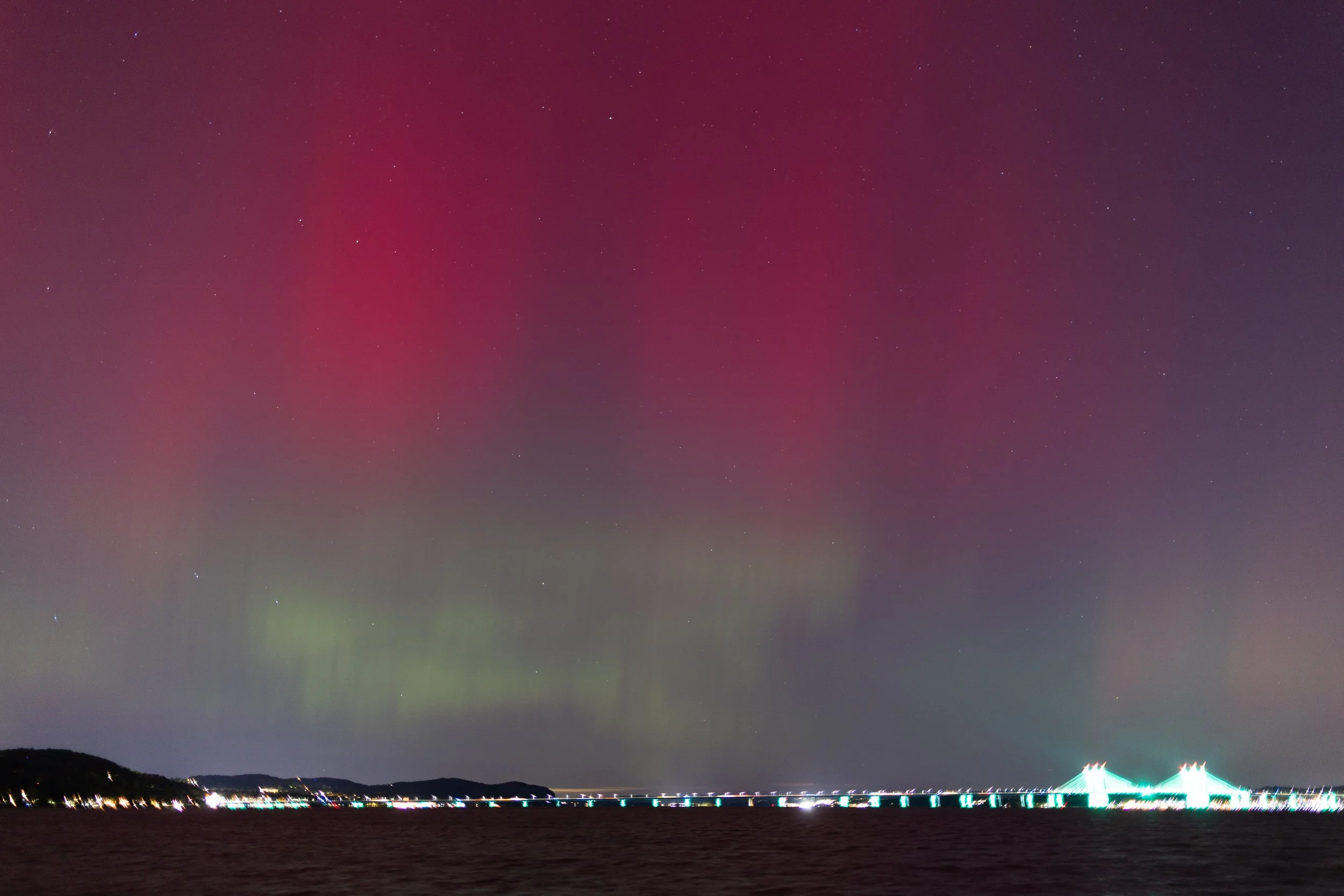
Aurora from Tappan Zee in New York, October 2024. F/1.4, 1.6sec, ISO 400
I like the photo from New York 2024 better. It shows a clear red / green division on the left which reverses on the right side of the frame. The image from Pennsylvania 2025 shows some red spikes but very little green. The aurora was brighter in 2024. The exposure I used for this (1.6 sec, ISO 400) is about 2 stops less than the one I used in 2025 (30.0 sec, ISO 100).
To photograph the aurora, I use a tripod and wide angle lens. For both of these, I used my Canon 24mm F/1.4L. I shot both of these wide open at F/1.4. I will choose the lowest ISO possible, usually 100, and choose a shutter speed that gives me enough light to start to see color. The colors vary a lot throughout the duration of the aurora, so I make sure to take lots of photos.
Aurora at Tappan Zee, 2024
In this shot from 2024, the aurora shows bright red above and lighter green below. The exposure is the same, F/1.4, 1.6 sec, ISO 400. The Mario Cuomo bridge is bright and overexposed in this shot.
Aurora from Hopewell Lake, 2025
The aurora at Hopewell lake was intermittently brightened by headlights from the nearby parking lot. In this shot, the trees on the other side of the lake are illuminated by headlights. Yet, the aurora and the stars are still visible.
When ever I come to a situation where I am not sure what camera settings to use, I think about what I care about. I brought my brightest aperture wide angle lens. So I use all the aperture I can: F/1.4. I want to minimize noise, so I start with low ISO. I use a tripod so I can use a long exposure. I choose the shutter speed to collect enough light for the situation. Between the two cases, I came to very different conclusions about what exposure value is needed. The aurora is highly variable from second to second, so it is luck of the draw.
Dumbo Tilt Shift
Took my tilt shift lens and tripod to Dumbo, Brooklyn. The first scene is the street with a view of manhattan bridge and empire state building. It’s an amazing shot that everyone and their mother is there taking. There’s even guy who will take your photo with a vintage polaroid camera. I am somewhat envious every time I see a bellows camera like that. But today I’m feeling fine with my Canon TS-E 24mm F/3.5L. I am also using a Leofoto G2 geared tripod head and a Sirui travel tripod.
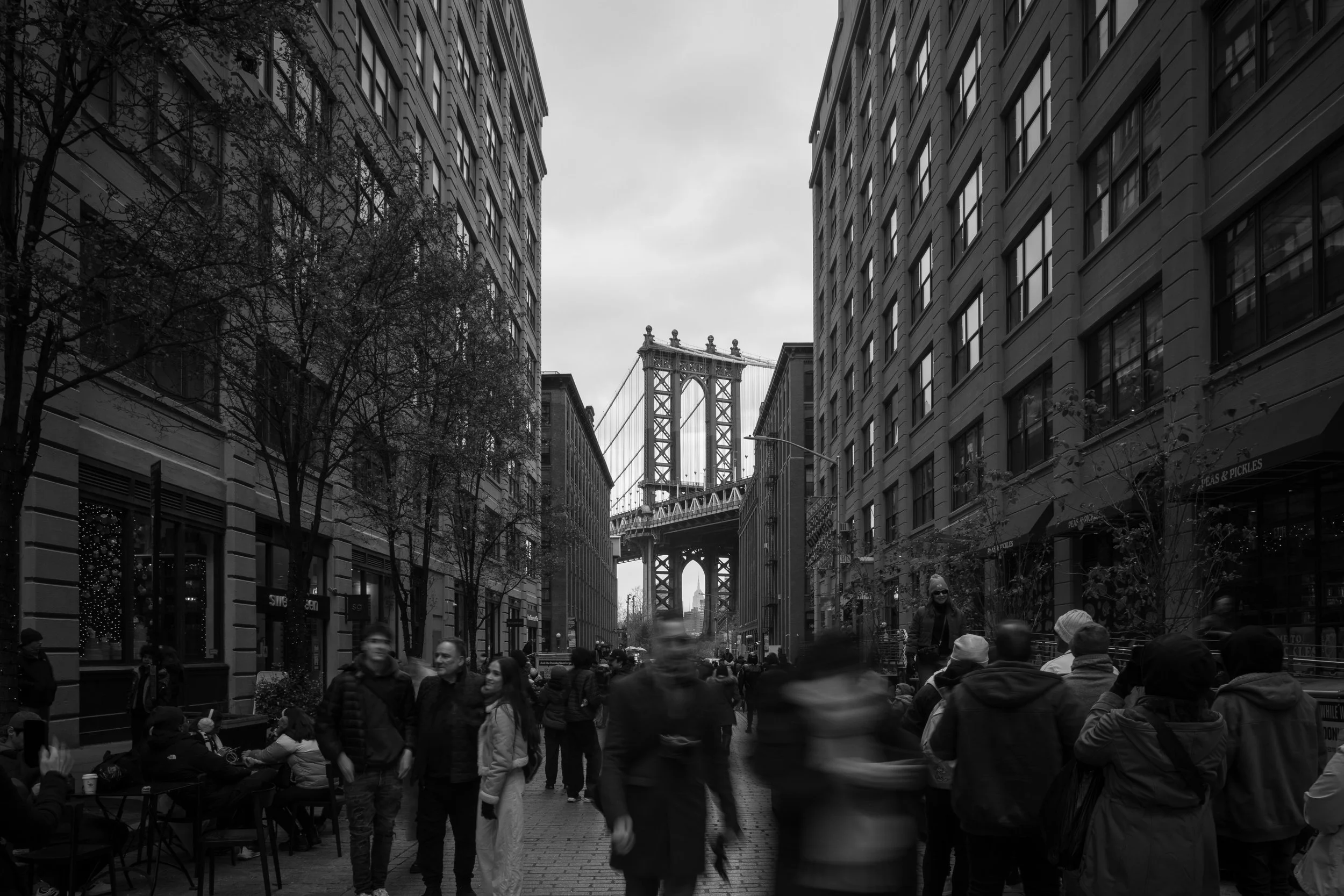
Washington Street, DUMBO
I place my tripod down, level my camera, and shift the lens upward. Not tilt, shift. Doing this with the shift movement allows me to recompose my shot without angling the camera upward. This is how the sides of the building and the structure of the bridge remain vertical and do not converge toward the top of the image. I used a polarizer, rotated to allow reflections on the windows, and used a very small aperture to obtain a long exposure. Exposure here was 1/5th of a second which causes the people to be blurred. I feel this gives a sense of rushing which I felt when I was there setting up this shot.
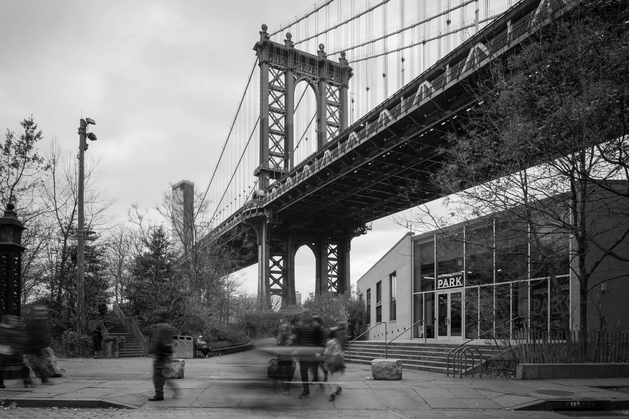
Brooklyn side of the Manhattan Bridge
Again, I leveled my camera to keep vertical lines vertical and recomposed using upward shift. The exposure time was still very long thanks to small aperture and polarizer darkening. The family there was standing and then moved during the exposure.
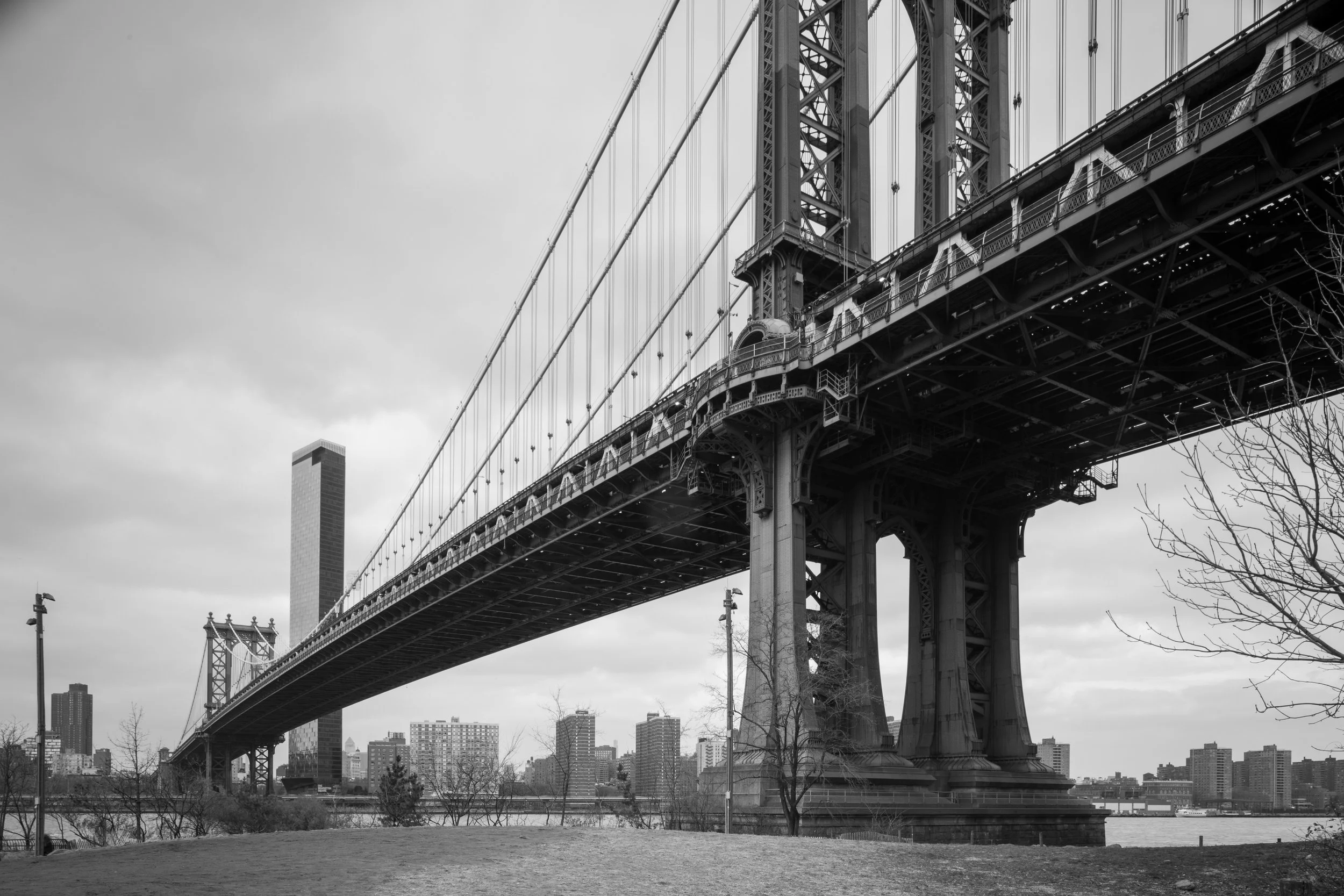
Manhattan Bridge
The base of the bridge is made of stone. The road way has a lot of metal. It is very loud when the train crosses this bridge. Again with correct perspective.
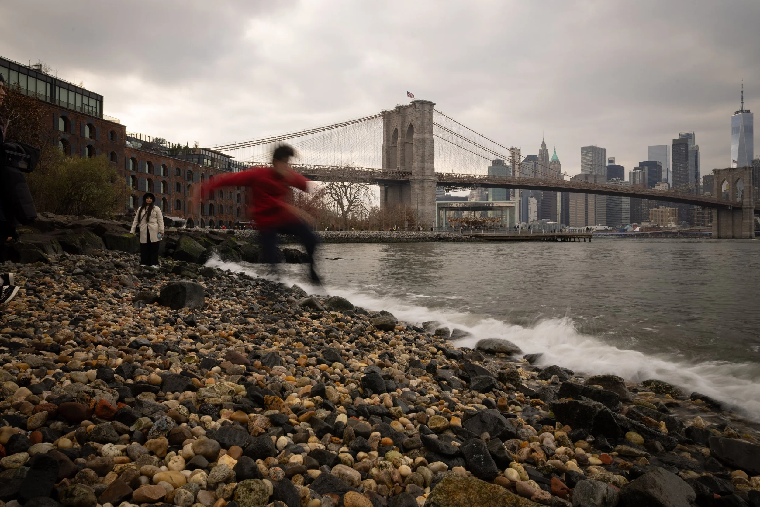
Boy skipping stones, Brooklyn Bridge
I set up the tripod with long exposure on pebble beach. The waves and the boy skipping stones turn blurry over the long exposure time. The Brooklyn bridge is in the background. One world trade center is visible on the far right.
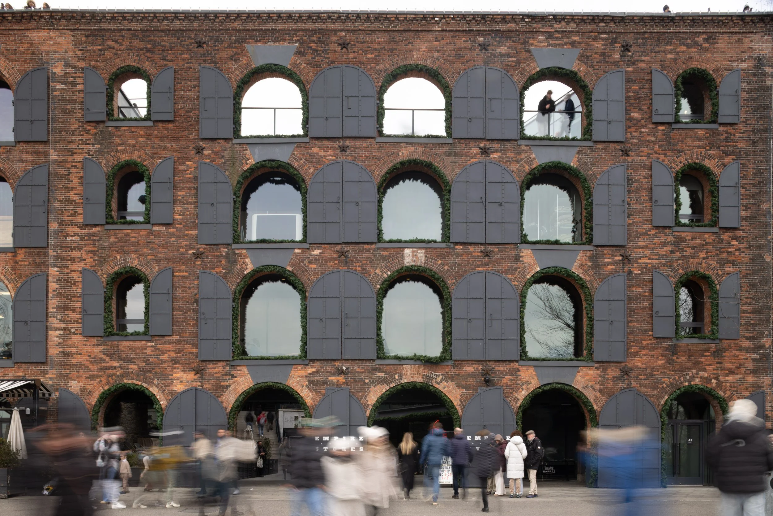
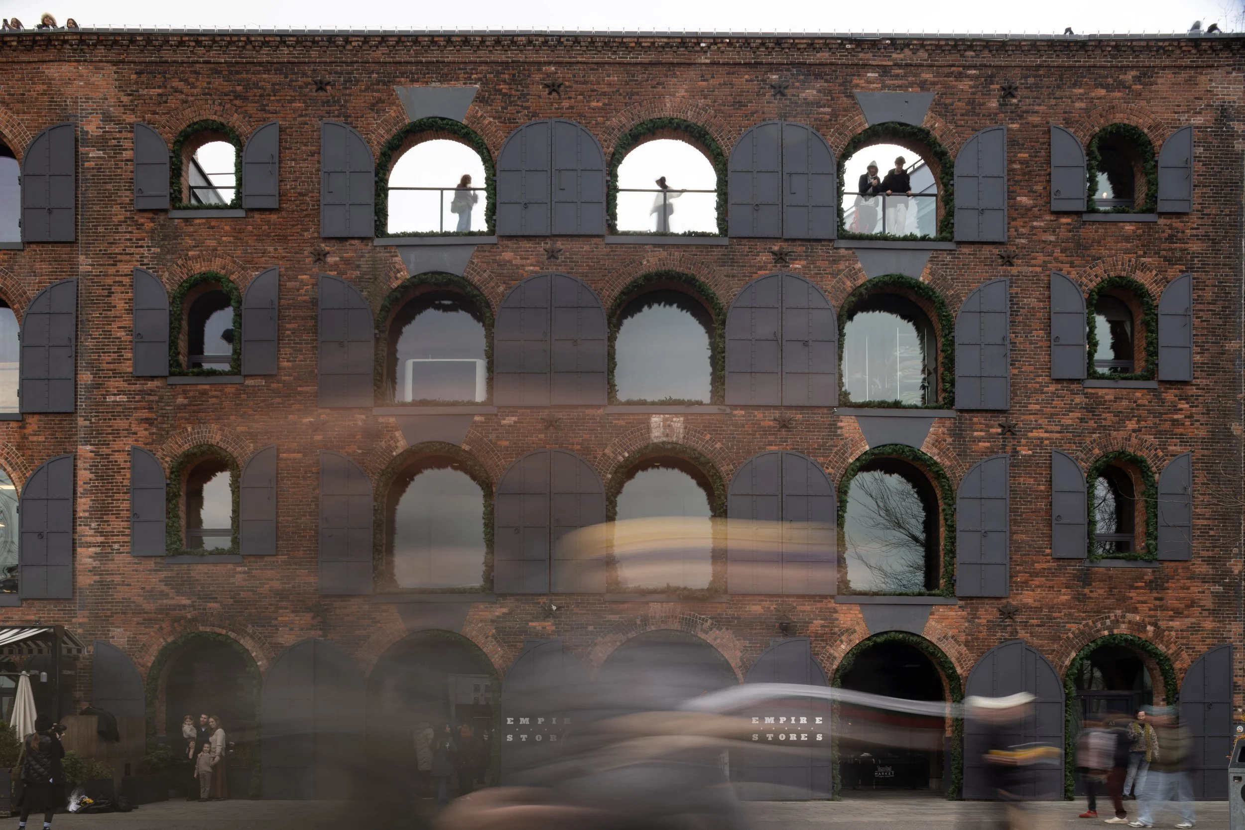
Empire Stores, Dumbo, Brooklyn
This brick fortress looking building housed fancy shops and a food court. There were thousands of people walking by. Over this 2 second exposure, the people blend into the background and appear ghostly. The rectangular grid of windows is maintained by perspective correction.
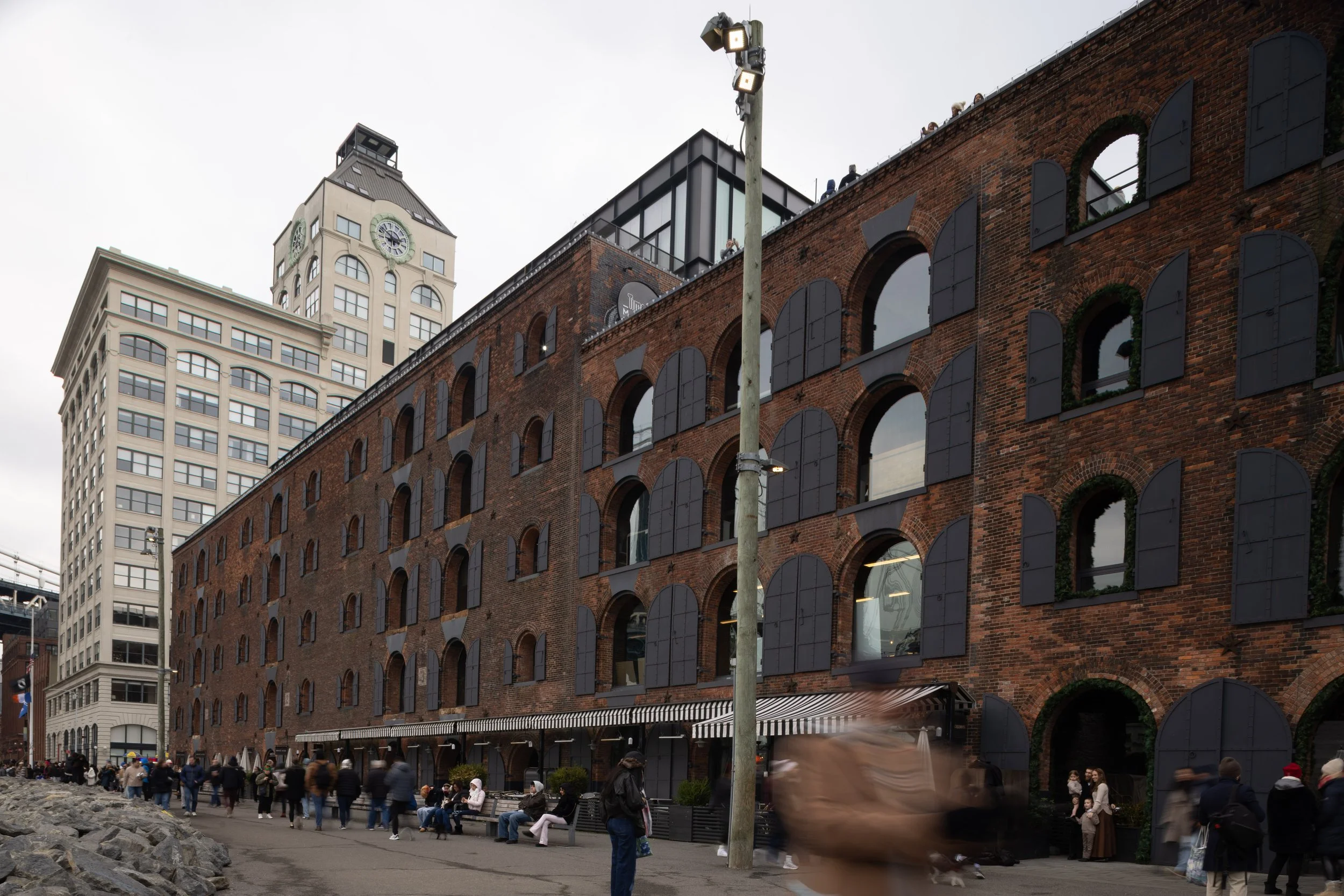
Empire Stores, Dumbo, Brooklyn
This is the same building with camera rotated to the left. Vertical shift is the same as in the previous shot.
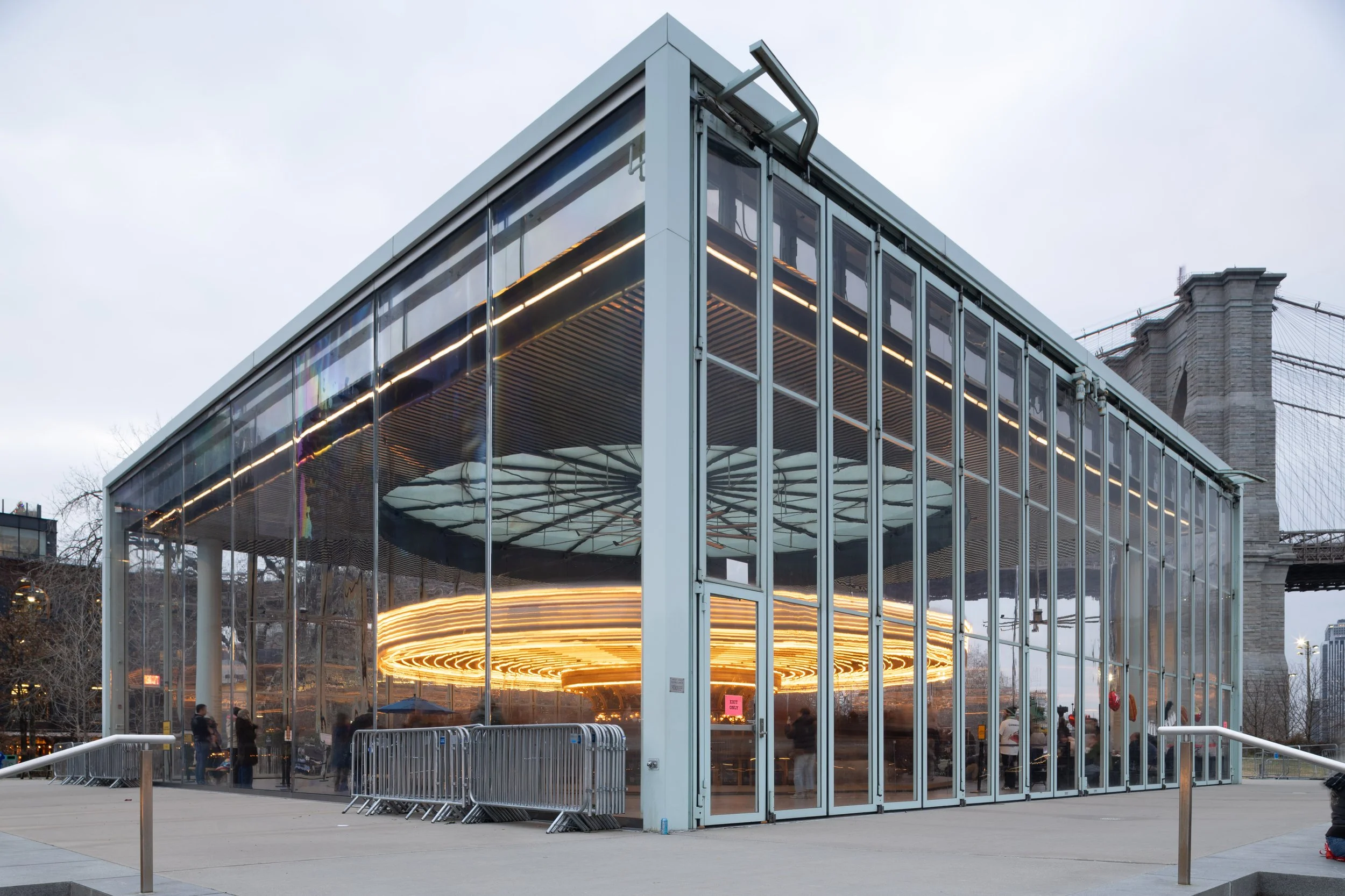
The carousel enclosed in glass
Jane’s carousel in Brooklyn Bridge park is housed in a glass building. The carousel spins and the lights create round trails in my long exposure image.
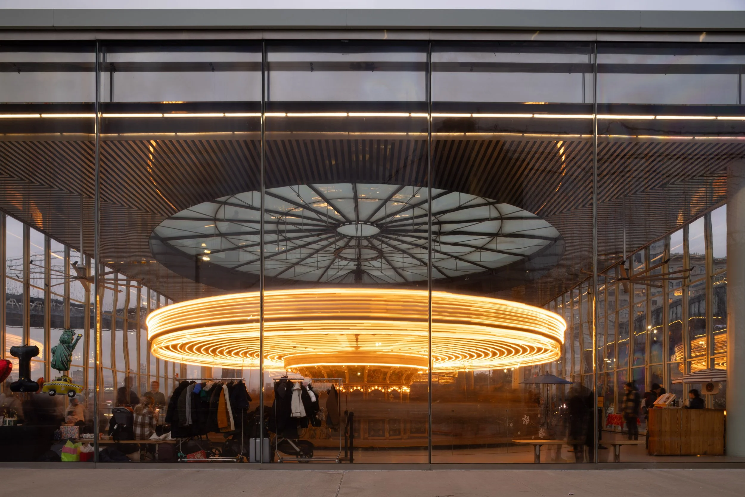
Carousel Spinning
In this shot, the camera is level and pointed perpendicular to the face of this building. The vertical and horizontal lines are maintained. The exposure produced nice elliptical light paths on the carousel. I love this shot.
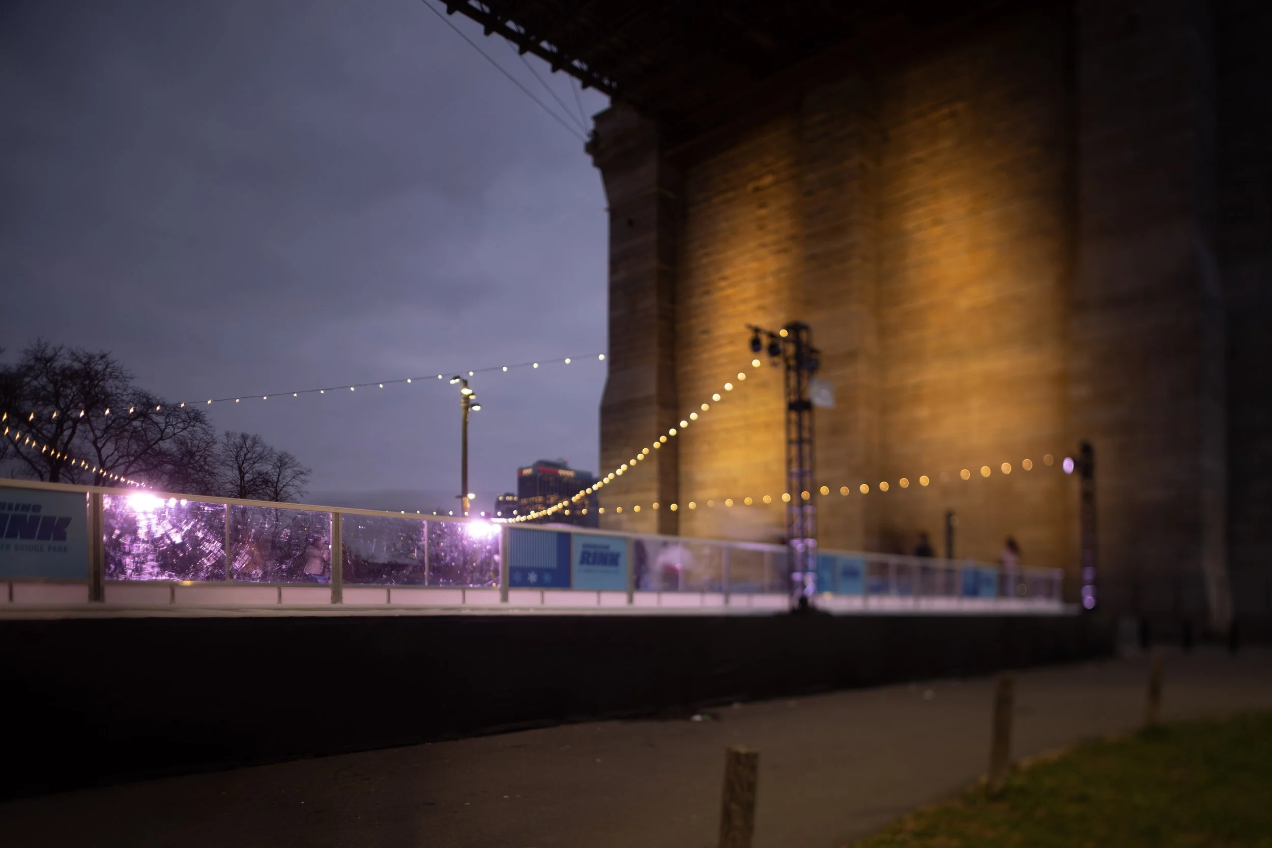
Skating Rink - Tilted Focus
The skating rink is nicely situated under the brooklyn bridge. I used wide open aperture and lens tilt to produce this wildly out of focus bridge while keeping some of the rink in focus. The miniature effect can be achieved with this type of lens tilt, but in this case, I think the bridge looks more surreal than miniaturized.
Tilting the Lens
When the lens is not tilted, the plane of focus remains parallel with the camera’s sensing plane. Tilting the lens tilts the plane of focus. The effect is that objects at different distances from the camera can all be in focus at once. Tilting the plane of focus the other way can result in radically defocusing some objects in the scene.
By angling the lens, the plane of focus is angled in the same direction to a greater degree. The rotation of the plane of focus is described by the Scheimpflug principle.
By tilting the lens, the photographer can obtain sharp focus over a whole plane that is not a constant distance from the camera. Tilting the opposite way allows the photographer to obtain the miniature effect in which the top and bottom of the frame are highly blurred which simulates the blur present in macro photographs.
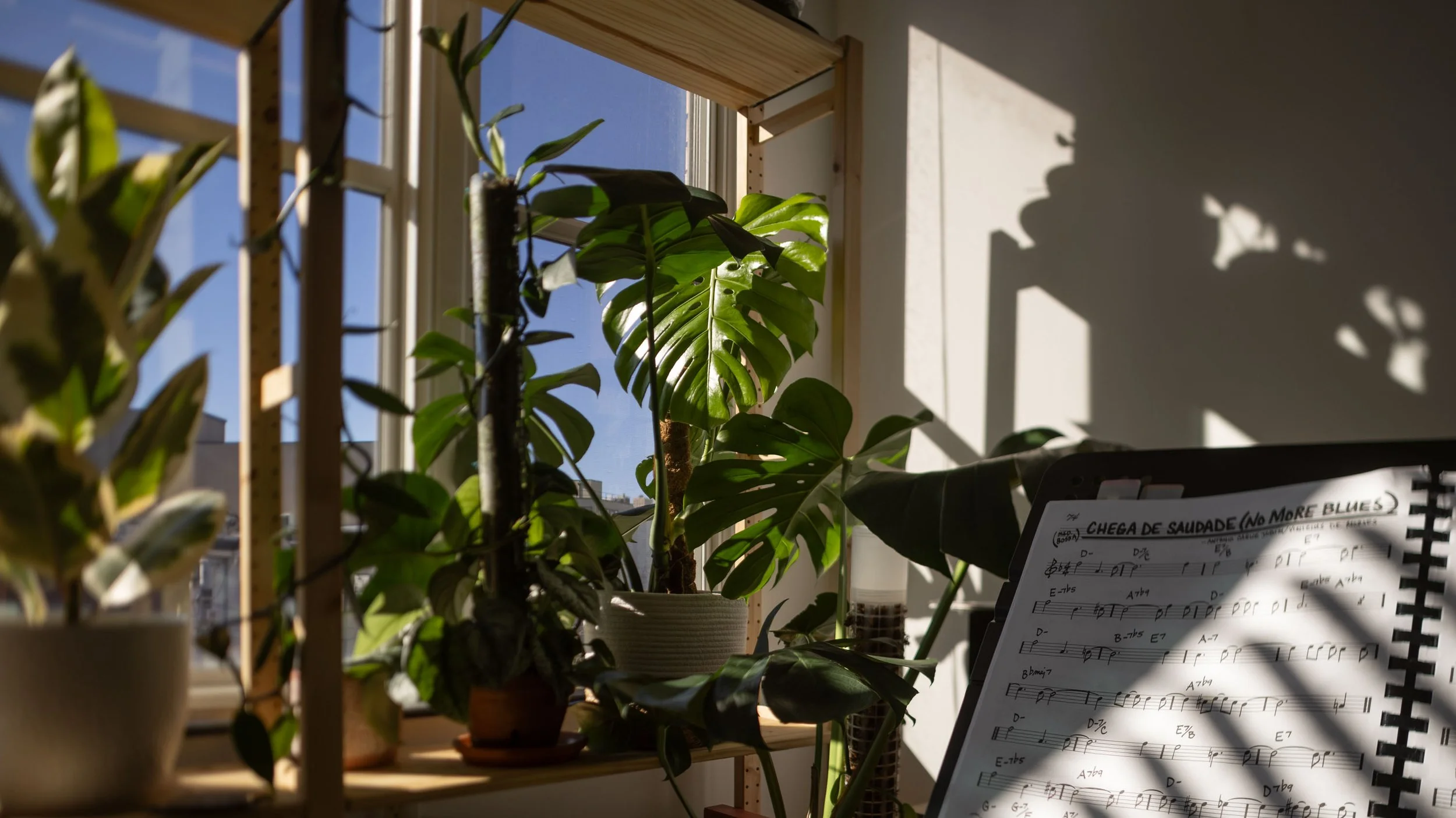
More things in focus
In this example, I obtain focus on objects that are different distances from the camera. In this scene, there is sheet music on the right that is in focus. The music is closest to the camera. The rubber plant is second farthest from the camera, but is out of focus. The monster plant is farthest away from the lens, but it is in clear focus. How did i obtain clear focus on the nearest and farthest subject, but not the middle depth subject? I tilted the lens to the right so that the plane of focus rotated to the right about a vertical axis. The altered plane of focus intersects the music and the monstera plant, but not the rubber tree on the left.

Scene of my living room with focus on foreground music stand and middle plant in background accomplished by tilting lens to the right. Canon TS-E 24mm F/3.5L
Fewer things in focus
The camera stayed on its tripod for this shot, so nothing about the scene has changed since the previous shot. The difference is that I tilted lens to the left. This made the plane of focus intersect only the monstera plane. This puts the sheet music and the rubber tree out of focus. The focal plane has rotated to the left.
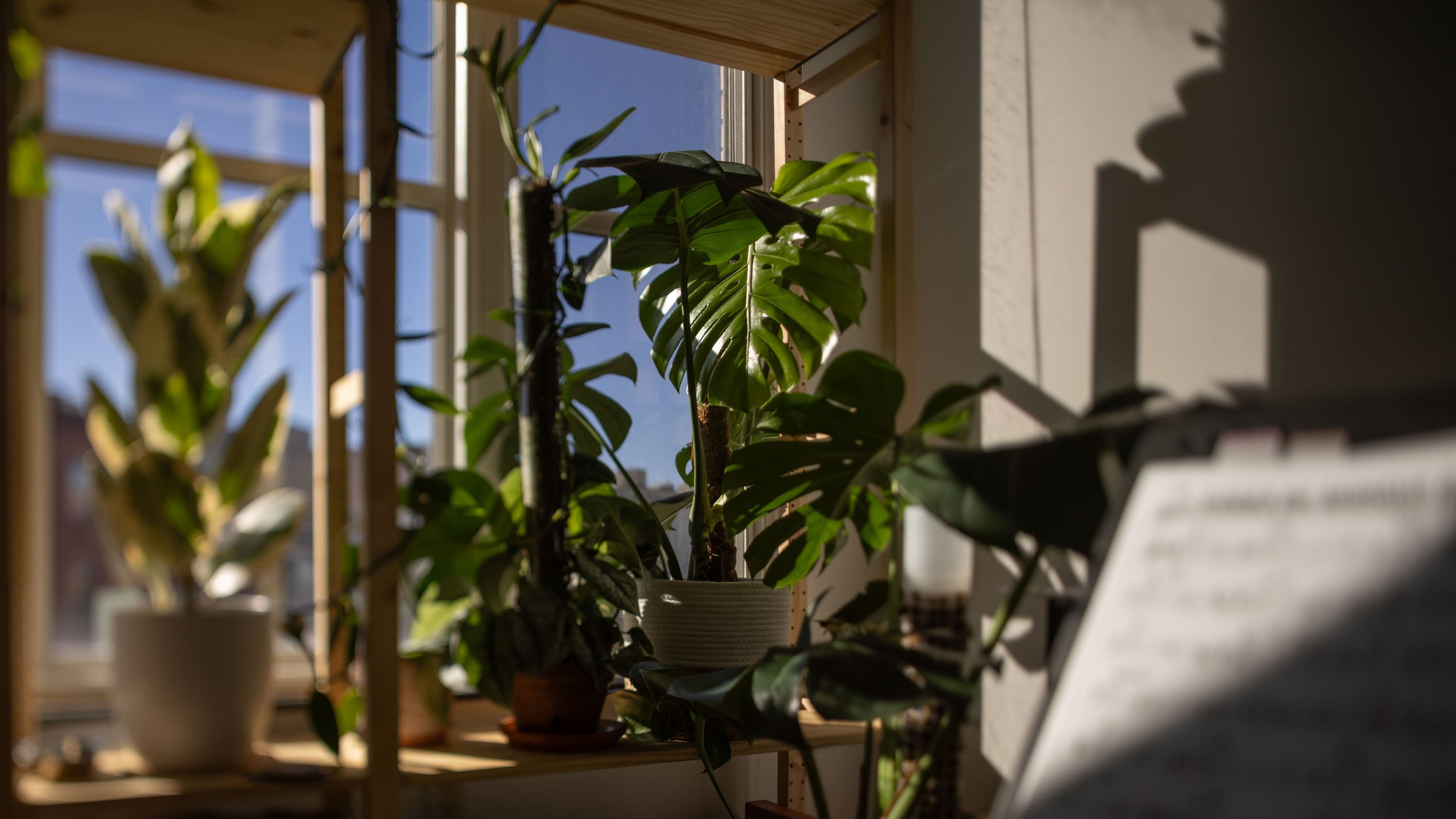
Scene of my living room with middle plant in focus and other subjects defocused by tilting lens to the left. Canon TS-E 24mm F/3.5L
Miniature Effect
Tilting the lens up or down can be used to achieve a miniature effect. Looking at small objects with high magnification results in very this depth of field. So, when we see object in focus and foreground and back ground out of focus, we associate this with high magnification of a very small subject. When the lens is tilted up or down to achieve a thin strip of focus on the subject and radical defocus of foreground and background, it can appear that the subject is miniature when it is not. In my example above, I have not achieved this. It is typically easier to achieve this with a 50mm tilting lens compared to the 24mm tilt-shift lens that I have used.

Scanner camera
Motivation
I first saw the idea of a scanner camera when I was in college around 2004. I was a camera enthusiast who used the art website Deviant Art, specifically its photography community. I saw a guy in eastern Europe create images from a flat bed scanner and a lens. Digital photography was fairly new at the time and the best cameras had around 6 MP. A flat bed scanner is slow, but has well over 100 MP which was very exciting at the time. But it wasn’t until 2024 that I started to build one of my own. Finally, I would live out my college boyhood dream of building a scanner camera. So, it was my turn to drill into a scanner and convert its purpose to that of a large format camera. What troubles would I run into? Would i be able to make a functional focusing mechanism? How would the images look?
The Lens
In January 2024, I was spurred to start the scanner cam project when I bought a Carl Zeiss S-Tessar 5,6/300 from ebay. The price of $28 was too good to pass up. This lens has a 300mm focal length. This type of lens is used for large format photography so I was sure it could cover an 8”x10” frame. I bought it with no aperture, so I would only have access to the wide open lens with aperture f/5.6. Now I needed a scanner of about 8”x10'“ scan area.

Carl Zeiss S-Tessar 300mm F/5.6 Large Format Lens
Scanner
I chose a Canon CanoScan LIDE 300. This was the cheapest functioning scanner I could find on ebay. It cost about $35. The scanner is USB powered so I knew I would not need to supply additional DC power. I could power the whole thing from my laptop. As we were taking apart the scanner to try to disable the illumination, we found that it won’t function without the white strip on the back of the glass in place. Because we lacked the ability to hack the scanner to operate without the illumination, we left the illumination turned on. Other scanner camera makers have found ways to disable the illumination so that it doesn’t interfere with picking up the light from the lens.
Camera Design
My design places the lens on the end of a long box with a flatbed scanner at the back. To focus the image, I designed a mechanism to move the scanner farther and closer to the lens. To focus the image at infinity, the scanner is held about 300 mm from the back of the lens. To enable closeup photography, the scanner moves to the back of the box as far as possible. The length of the box, and size of the movement mechanism, dictate the minimum focus distance of the scanner camera.
The movement mechanism was purchased as an adjustable height laboratory stand. My plan was to screw the scanner into one end of the lab stand and connect the bottom of the stand to the back of the box. The knob for adjustment works to adjust focusing distance for the camera.
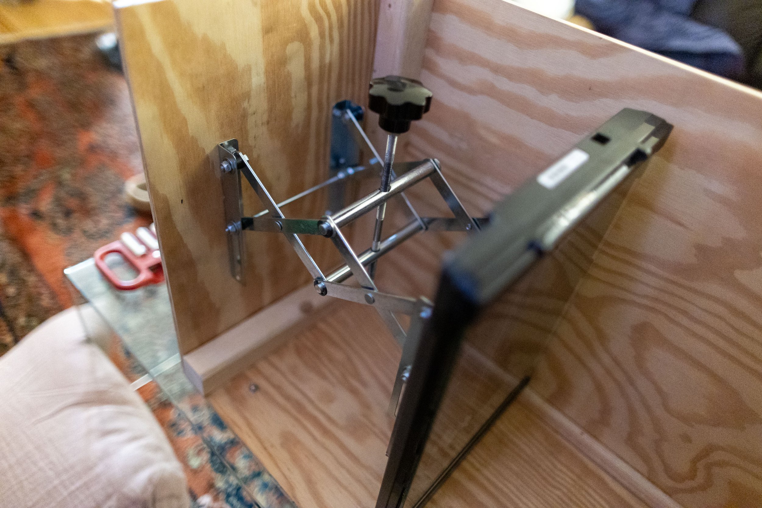
The focusing mechanism inside the wooden camera box. no focusing motor is installed so focus knob adjustment is manual.
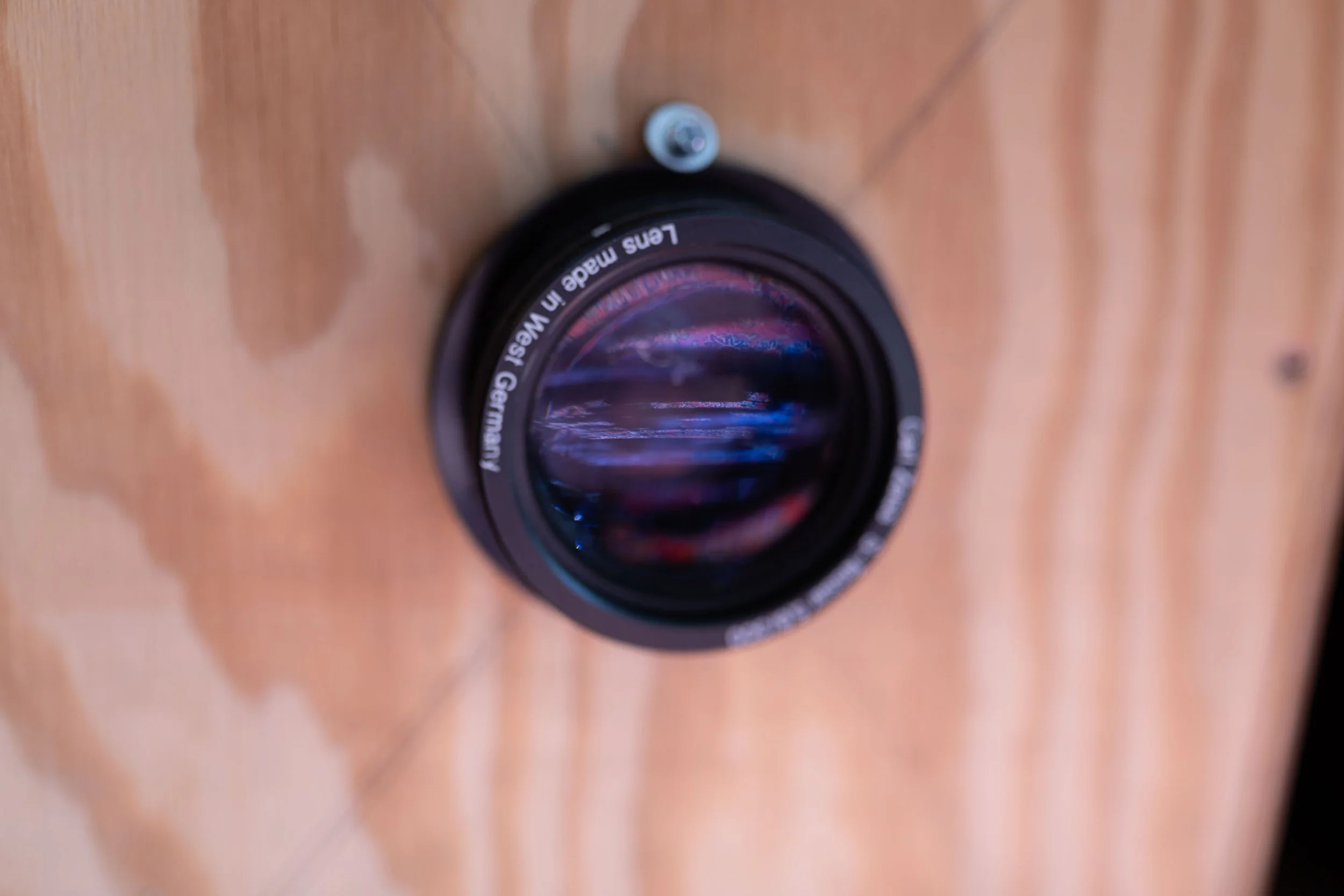
The lens installed the wooden camera box
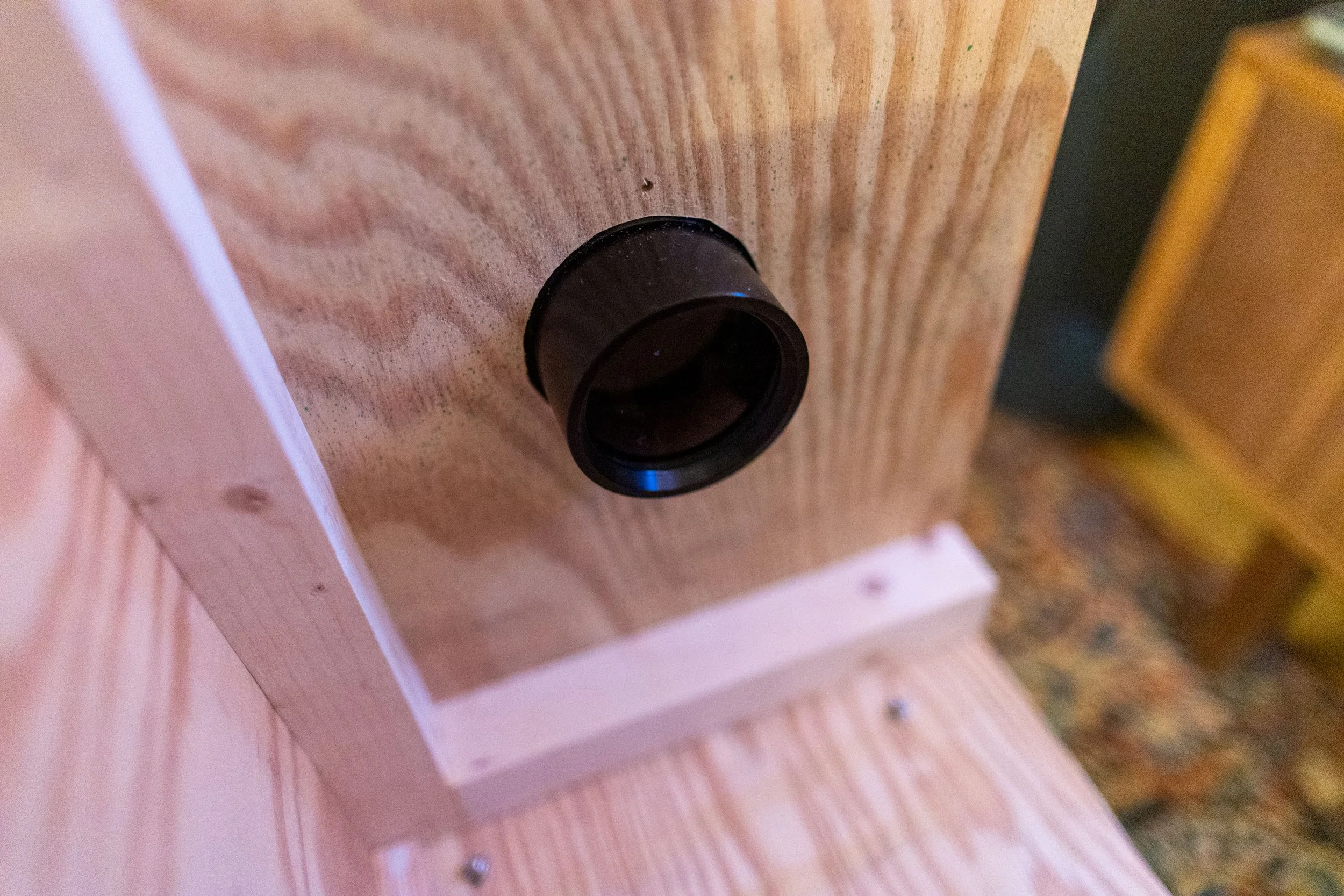
The backside of the lens installed into the camera box
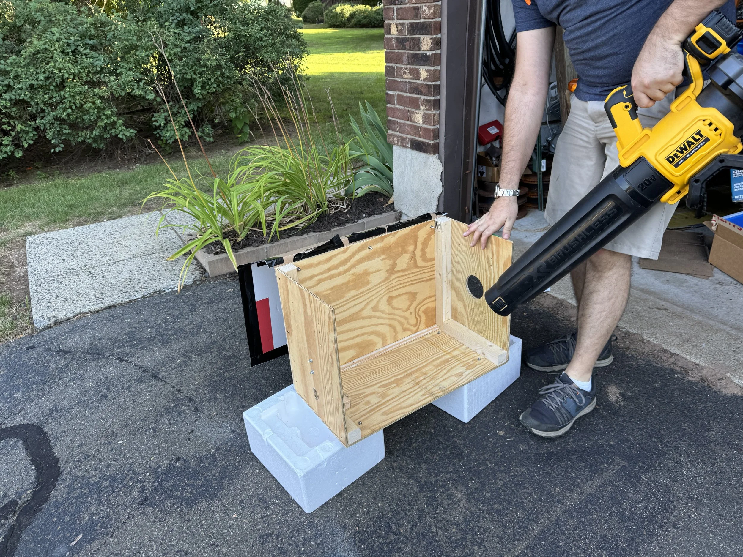
Painting prep on the wooden camera box
Thanks to Steve for the help and use of his shop to build the box. I couldn’t have done it without him.
Camera Usage
Portrait Photography
The lens does not have the usual aperture adjustment present on most lenses. So, diameter of the lens is fixed and the brightness of the image cannot be reduced. If a scene has too much light, the image will be overexposed. In the following image, my parents are illuminated by natural light on a screened in porch, just slightly too bright for the scanner to handle. This resulted in the overexposure in their faces and the background. I really like the vignetting and the weird background texture. The vertical bands inherent to the scan interact with the out of focus porch screen texture to create a unique pattern.
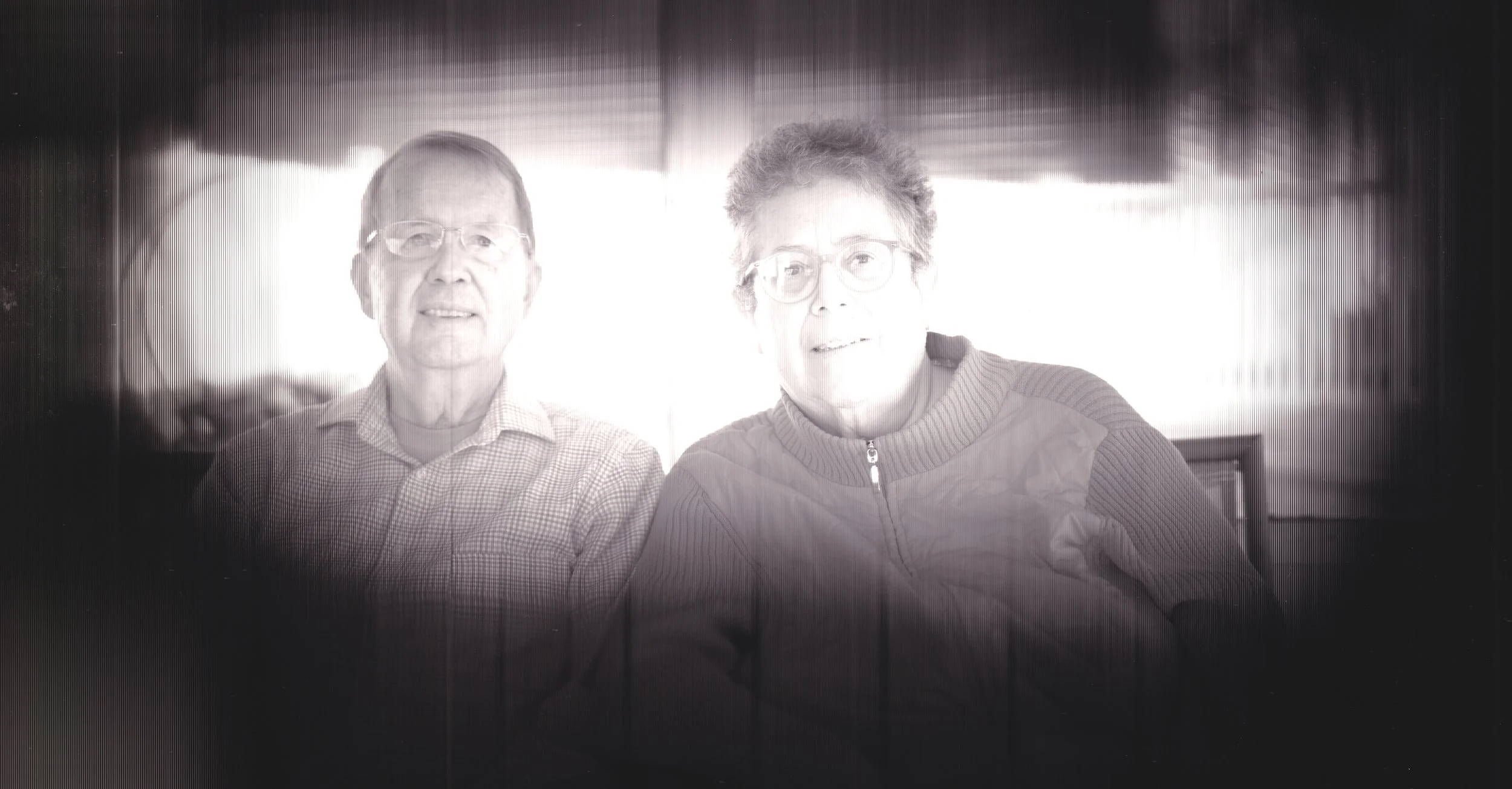
My parents, image from the scanner camera
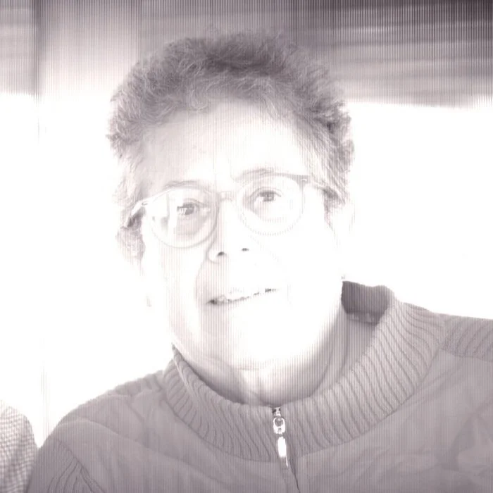
Closeup of my my mom’s face
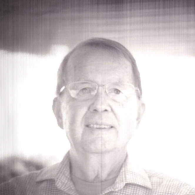
Close crop of my dad’s face
Focusing Demonstration
What does the image look like when it’s projected onto the scanner? To answer this question, I hold a pad of paper onto the scanner bed. Partially closing the lid blocks most outside light still allowing me to point my video camera inside. As I rack the focus from infinity to macro, you can see the focus go from the buildings outside my window to the plants in front of my window. As expected, the image is inverted and the buildings are at the top of the image.
Calculating Maximum Magnification
To focus at something infinitely far away, move the scanner bed to about 300 mm from the lens (the focal length). To focus closer, move the scanner to toward the back of the box. When the scanner is in the back of the box, the scan bed is about 445 mm from the lens plane. The lens focal length is 300 mm. Using the Gauss thin lens equation, the focusing distance will be 920 mm from the lens. F = 300 and S’ = 445, so S = 920. This means that the maximum magnification produced by this camera is .48:1 (m = 445 / 920 = .48), or approximately 1:2. This means that when camera is set to minimum focusing distance, the image is about half the size of the object being photographed.
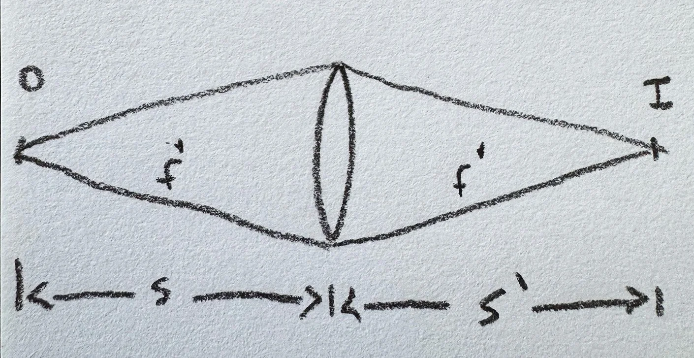
Diagram of a lens forming and image of an object with distances s, s’ labeled.
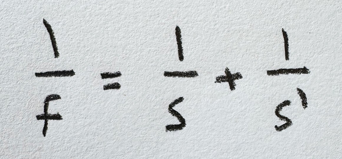
Gauss thin lens equation
Closeup photography
In this image, I photographed a succulent plant Crassula Ovata “Gollum”. It is putting out a new pair of leaves above the lowermost leaf on the left. The trunk is starting to turn from green to a calloused brown. The image shows the new leaves in clear focus and the texture of the trunk is visible. There is pleasing blur on the edges of the pots that are not in the plane of focus.
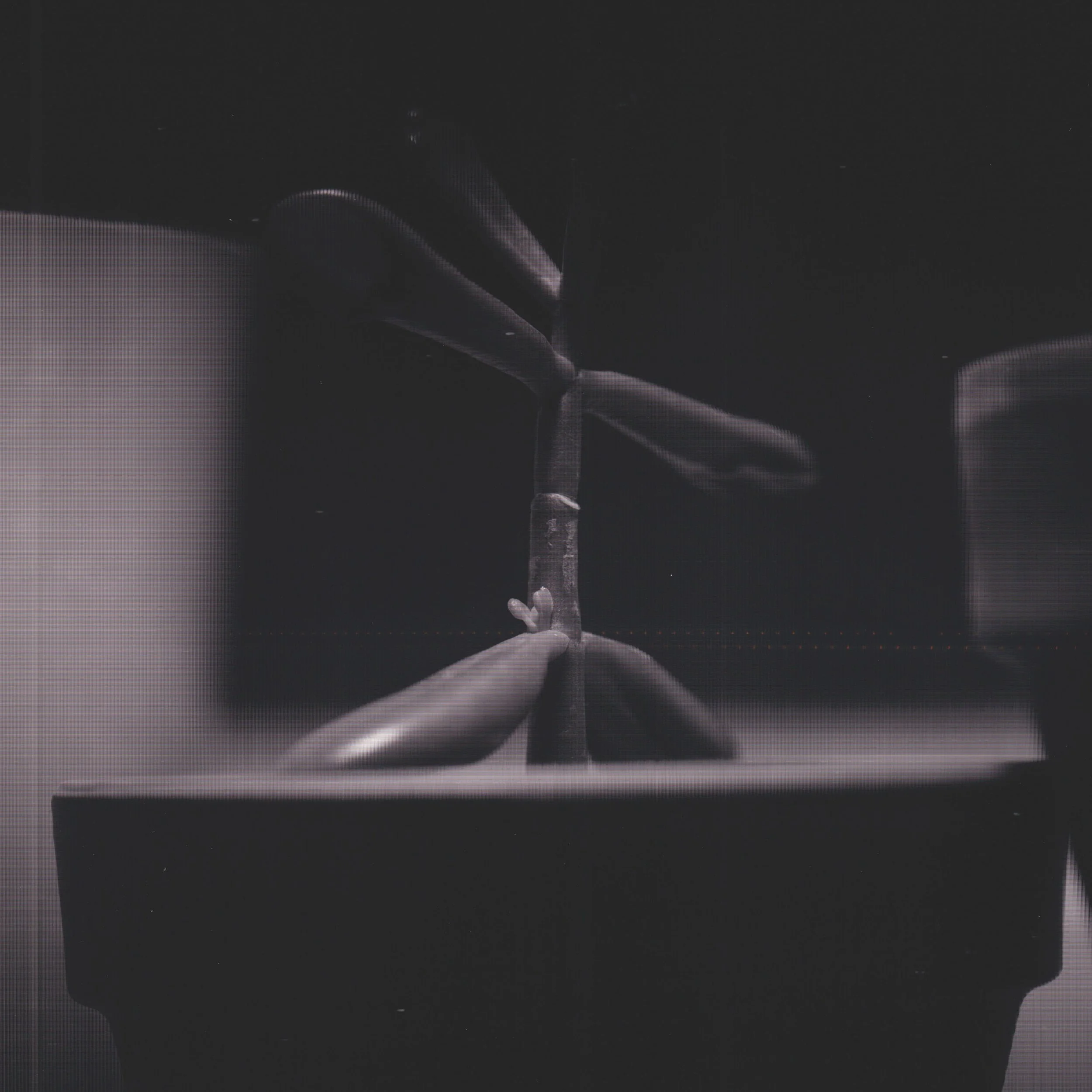
Crassula Ovata Gollum. Closeup photo with the scanner camera
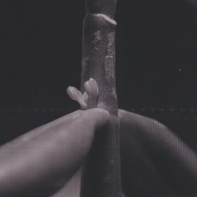
Closeup of the new leaves, 100% crop
Vignetting
One problem with the camera is that most of the image area is black. Visually, you can see the image projected over the entire scanner bed with a piece of paper taped on, as shown in the video before. Therefore, the lens is providing an image over the whole scan area. The likely reason for the vignetted images is the angle of the light from the lens as it enters the scanner. Light near the middle is entering nearly perpendicular to the scanner. While light reaching the edge of the scanner comes in at an angle, not perpendicular. My guess is that the sensor in the scanner is made to be insensitive to off angle light. This would keep the scanner focused on a small area of a document. But as a camera, this is not ideal.
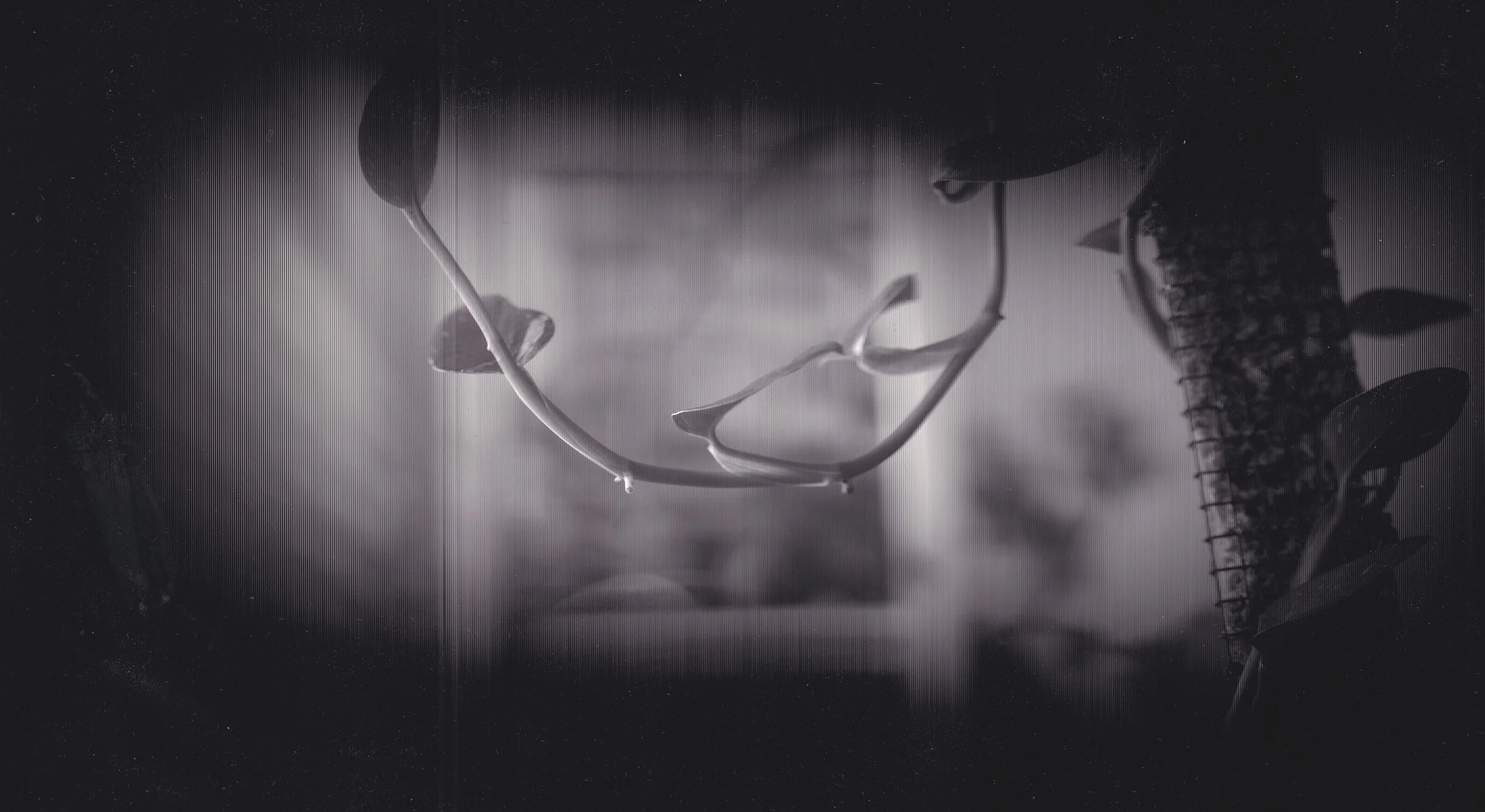
monstera standelyana vine hanging down. photo taken with scanner cam.
Some people have suggested using a fresnel lens on the scan bed to refract the light into the axial direction, the direction that the scanner should be most sensitive to. I have not obtained an A4 size fresnel lens, so the best images I have capture thus far have been highly vignetted. The following image is the full width of the scanner (about 8 inches) and is cropped in the vertical dimension from about 11 inches down
Focusing Motor
I wanted to be able to focus the scanning bed without manually adjusting the focus knob. I wanted a switch to activate a motor to drive the focus mechanism. So I designed a DC circuit that powers a motor for this purpose.
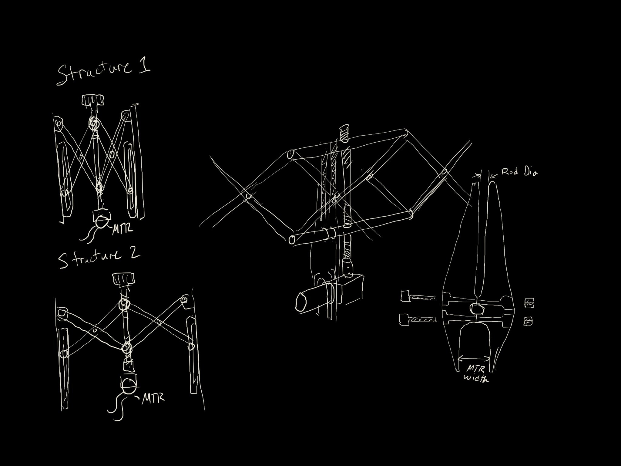
Drawings of a motorization design for the scanner movement mechanism
The stabilizing frame that reacts the motor torque into the upper bar of the lifting assembly is made of plywood. We initially tried 3D printing this piece but ran into technical difficulties in the print. So we switched the design to plywood to make it work. This piece is required to prevent the gear motor from spinning around in the box when the voltage is applied. The switch on the back of the box is a double pole double throw switch (DPDT). This type of switch allows me to reverse the polarity of the voltage on the motor, enabling adjustment in both directions. When the scanner is near the middle of the box, focus is at infinity. when the scanner is at the back of the box, focus is closeup.
Cost
The project was completed in two phases. Phase 1: creating the box with lens, scanner, and focusing assembly was completed in Q1 of 2024. Phase 2: building the DC circuit and focusing motor assembly, installing motor and control assembly, installing brass handles, was completed in Q3 of 2024. The total cost for components was about $163. The price of this lens seems to be a bit higher now. I would recommend a different scanner. Try to find one with a RGB sensor so that the images from the scan will have color information. This type of scanner has a monochromatic sensor and pulses RGB lights at the document to resolve color information. This type of sensor cannot resolve color information from continuous light sources. This might mean choosing a very old scanner. One that might have been available in 2004 when the original scanner camera was built. Also, 3D printed housings might be a better choice than plywood, which is heavy and expensive.
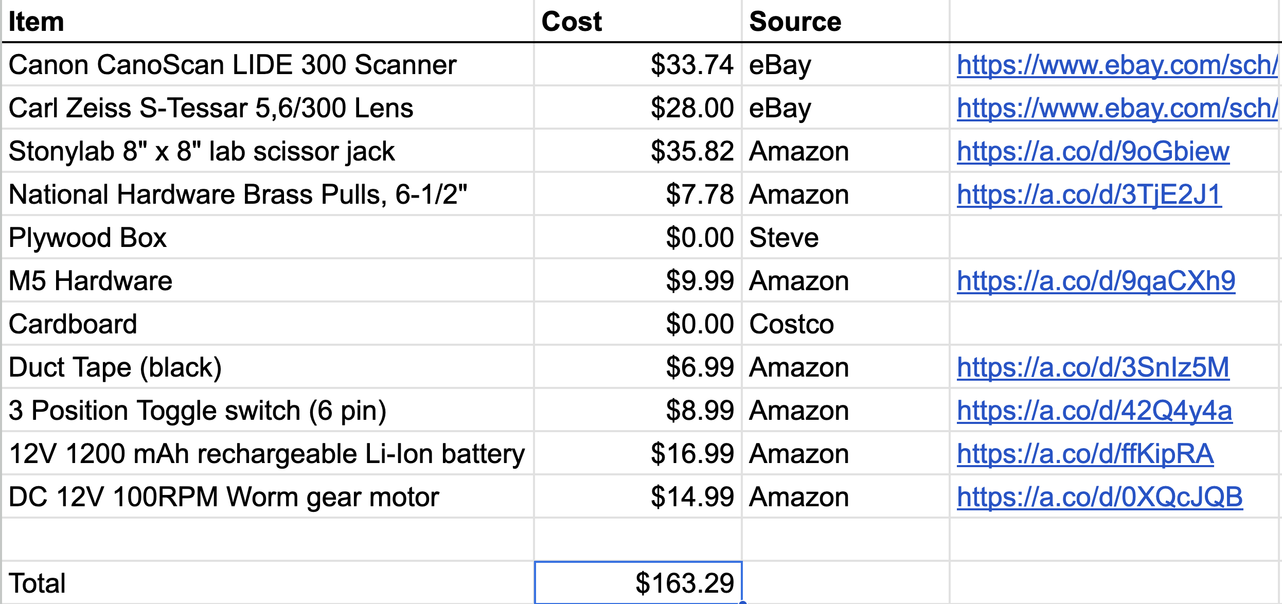
Bill of Material for the scanner camera build
Thanks Steve
Steve and I started our aerospace engineering careers around the same time. We have been friends for many years. We used his basement shop to build the box for the camera. Thanks Steve!
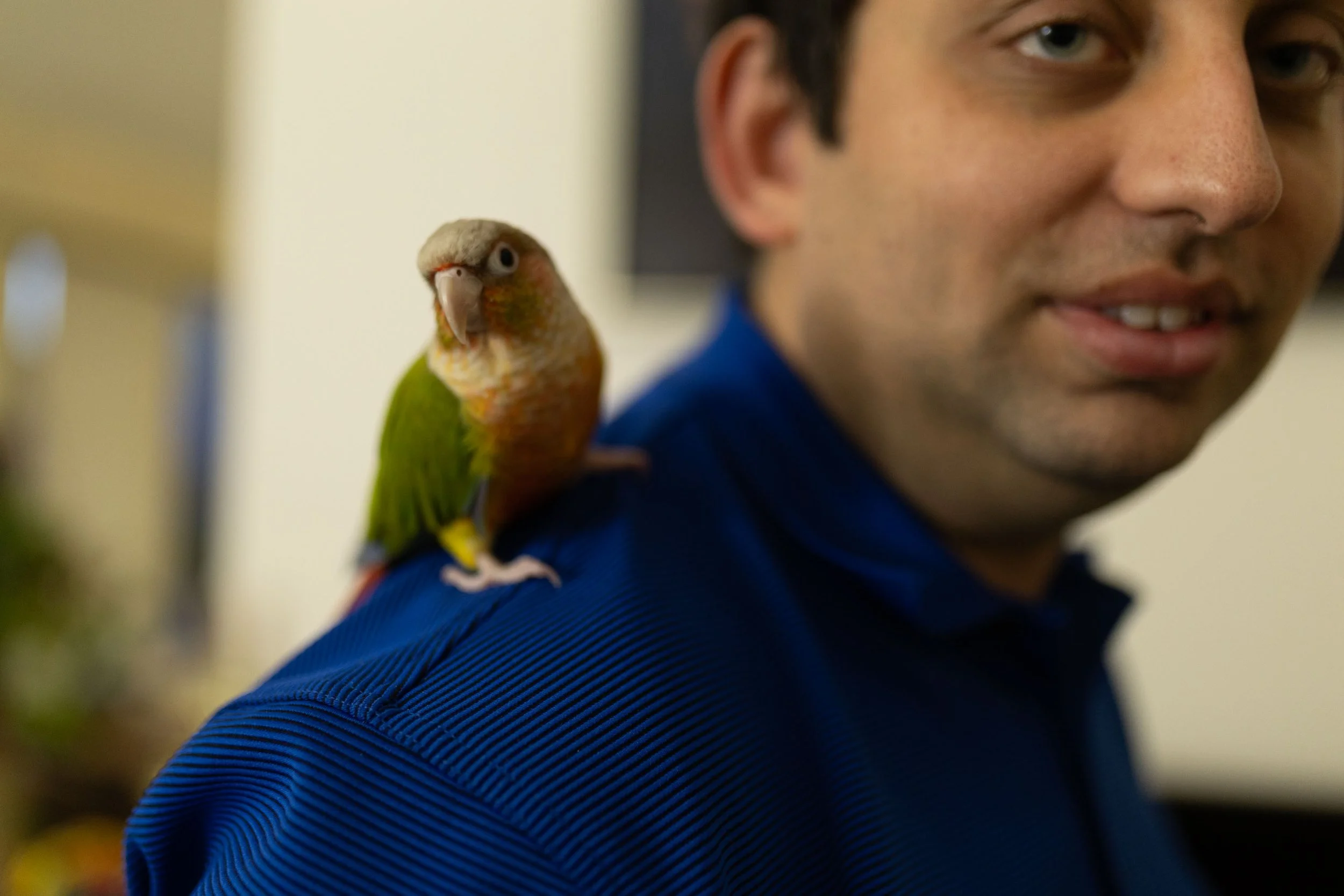
Steve and Chirp

Controlling Perspective
post that considers perspective control and how to control vertical lines in images by leveling the camera
The image we typically have of buildings, and things that are above us, usually gives more weight to the lower part of the object. By tilting our head upward, the lowest part of the object appears larger and the upper part of the object appears smaller. In the scene below, the edges of the building are parallel and perfectly vertical. But in the image, the lines that correspond to these edges are not parallel. These lines converge toward a point above the top of the image. This phenomenon is due to perspective projection. The lens in our eye, and our cameras, projects an image onto a sensor. In our eye, the retina is the sensor that reacts to light projected from the lens at the front of the eye. In our camera, we project an image onto a CMOS sensor using a lens. How does projection work and why does it change the size of parts of our image?
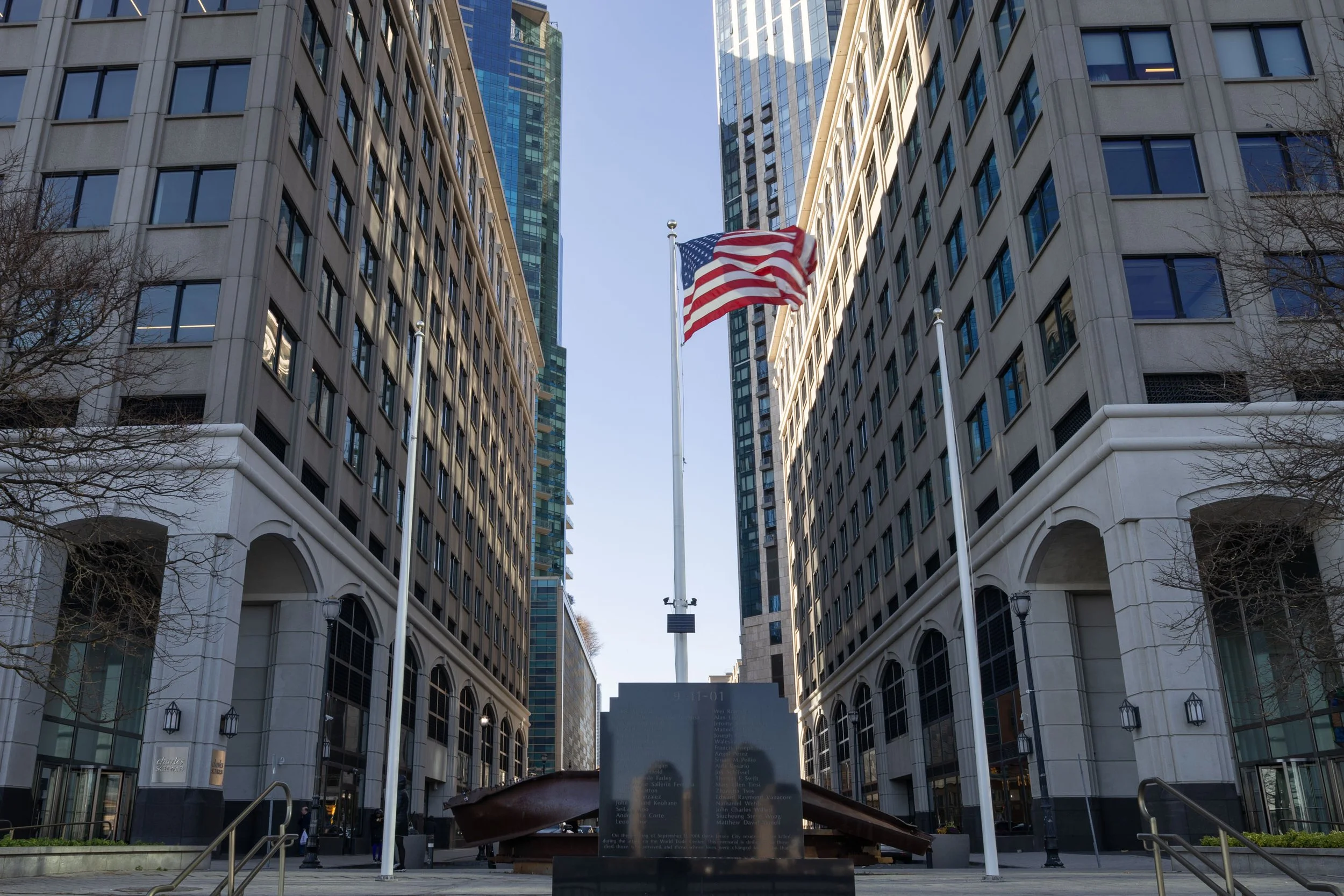
Image of the 9/11 Memorial at Exchange Place, Jersey City. Camera tilted up so that parallel edges of the building converge toward the top of the frame. The “natural” view.
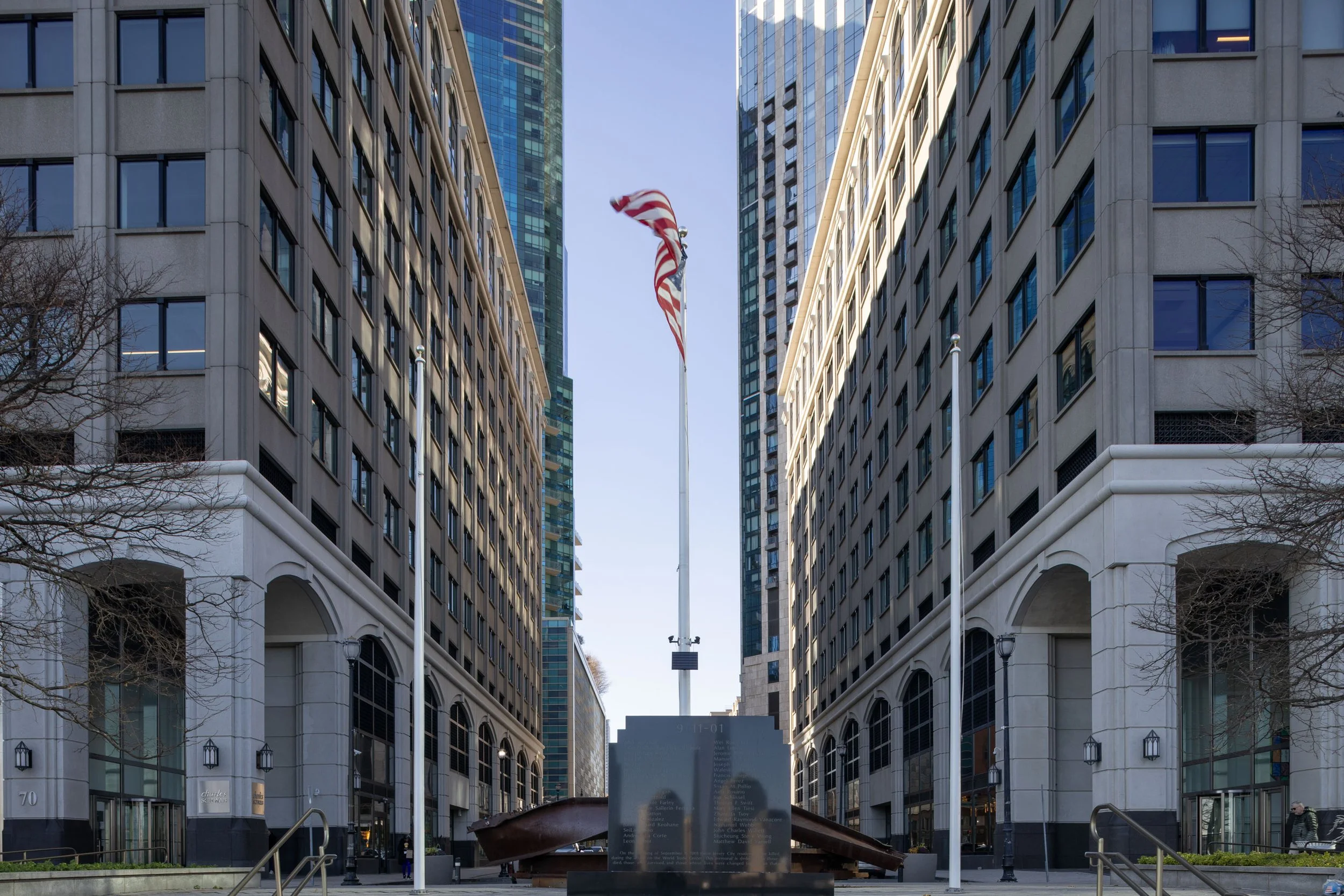
The 9/11 memorial at Exchange Place in Jersey City. Perspective corrected by leveling the camera and adjusting composition using lens shift movement. Lens: Canon TS-E 24mm F/3.5L
To obtain the perspective corrected image of the memorial, I leveled the camera in two planes, so that the camera was free to rotate about a perfectly vertical axis. I then rotated the camera about this axis until the optic axis of the lens perpendicular to the plane of the building. These steps of camera setup ensure that the sensing plane of the camera is parallel with the building facade. The consequence of perfectly leveling the camera the flag is cut off in the image. To correct this, I used upward lens shift. Lens shift can be obtained on tilt shift lenses.
Why does this happen?
A perspective projection is a map from a set of 3 dimensional points (points in the world) to a set of 2 dimensional points (in the image) that satisfy a condition. In the case of the pin hole model of the camera, the condition is that points in the 2D image correspond to points in the 3D space through straight line segments passing through the pin hole. So images are formed by a bundle of rays, passing through a single point, connecting objects in the 3D world to points in our 2D image. This is the pin hole model of the camera. Below is a diagram of points in an object projected into an image.
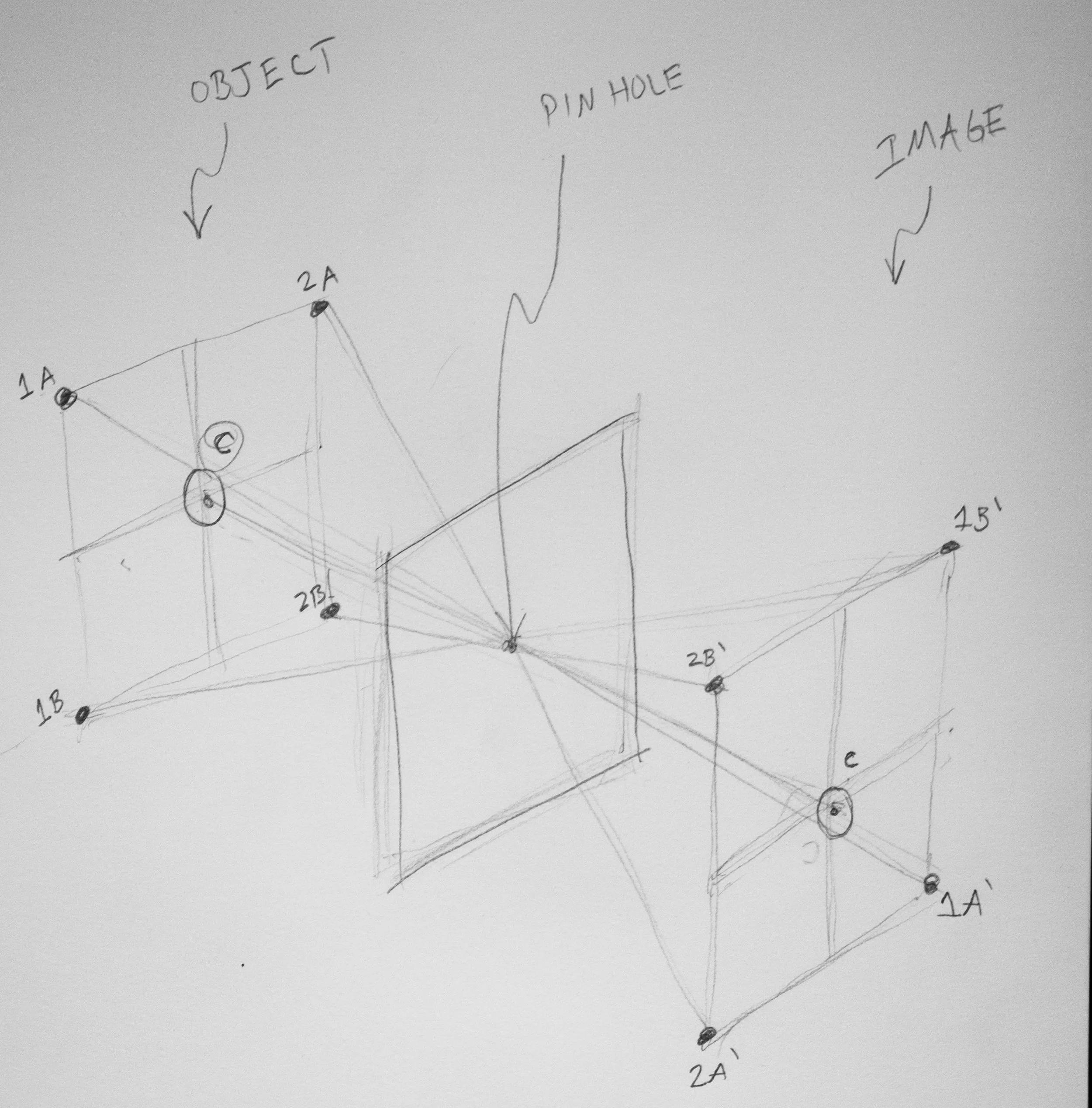
Diagram of points C, 1A, 1B, 2A, 2B projected through a pin hole to form their images C’, 1A’, 1B’, 2A’, 2B’
The perspective is controlled by the location and direction of the lens and its relation to the sensing plane (film or sensor). So, the most important perspective correction tool is not a perspective control lens. The most important tool is a tripod, preferably with a geared head and a bubble level. Most cameras today come with electronic levels that can display the angle in both pitch and roll directions. In the following video I visited New York City’s lower east side where I’m using a tripod with a geared head to demonstrate how to level the camera in two planes.
Perspective can drastically shape the way objects are perceived in an image. So if I learn to control it, I can control the relative size of objects in the scene. And I can control the perspective by changing the position and direction of the camera. By tilting the camera upward, what was a rectangle becomes a trapezoid. Leveling the camera keeps vertical lines vertical.
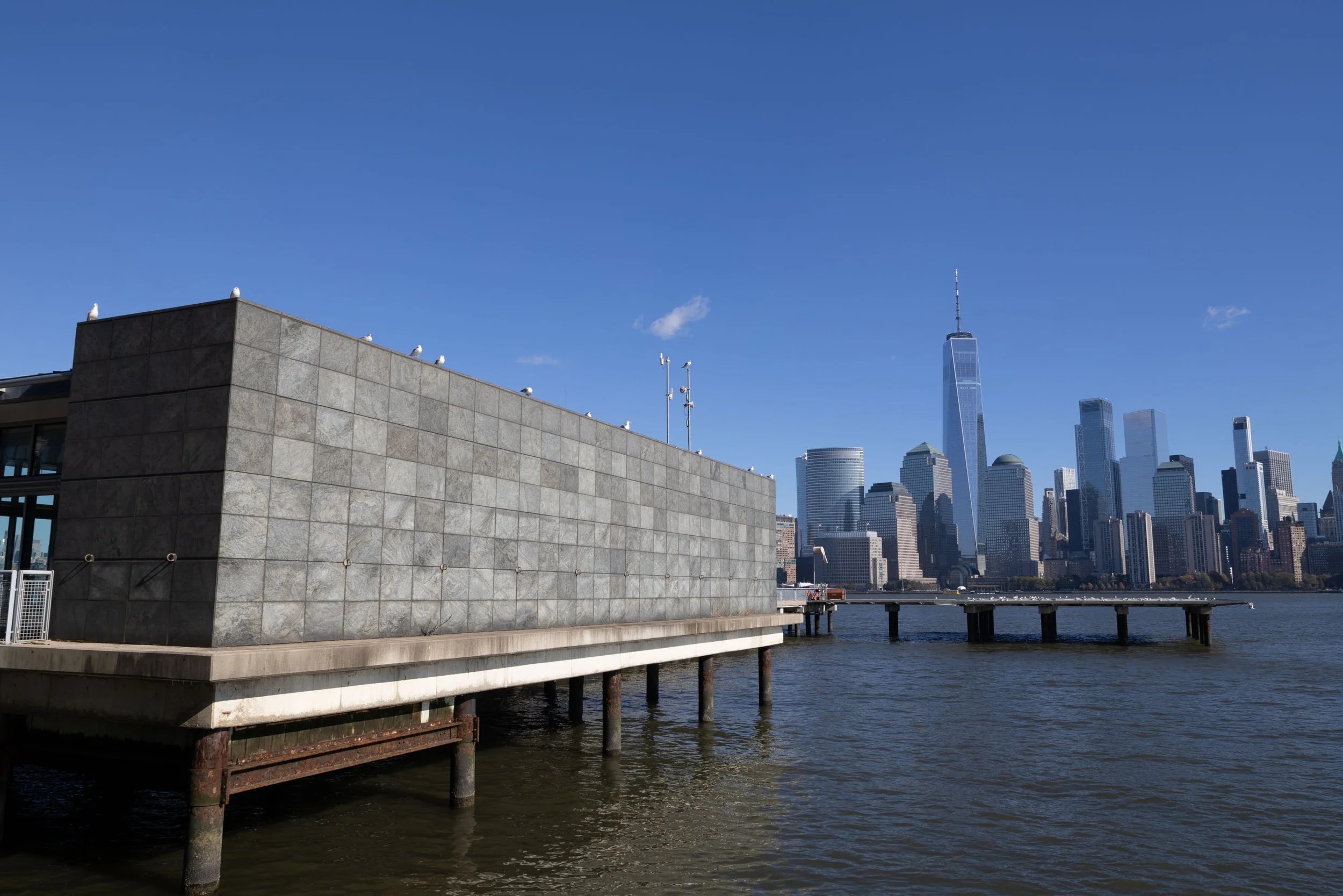
Paulus Hook Ferry Stop, Camera is tilted up slightly. vertical edges are converging lines in the image
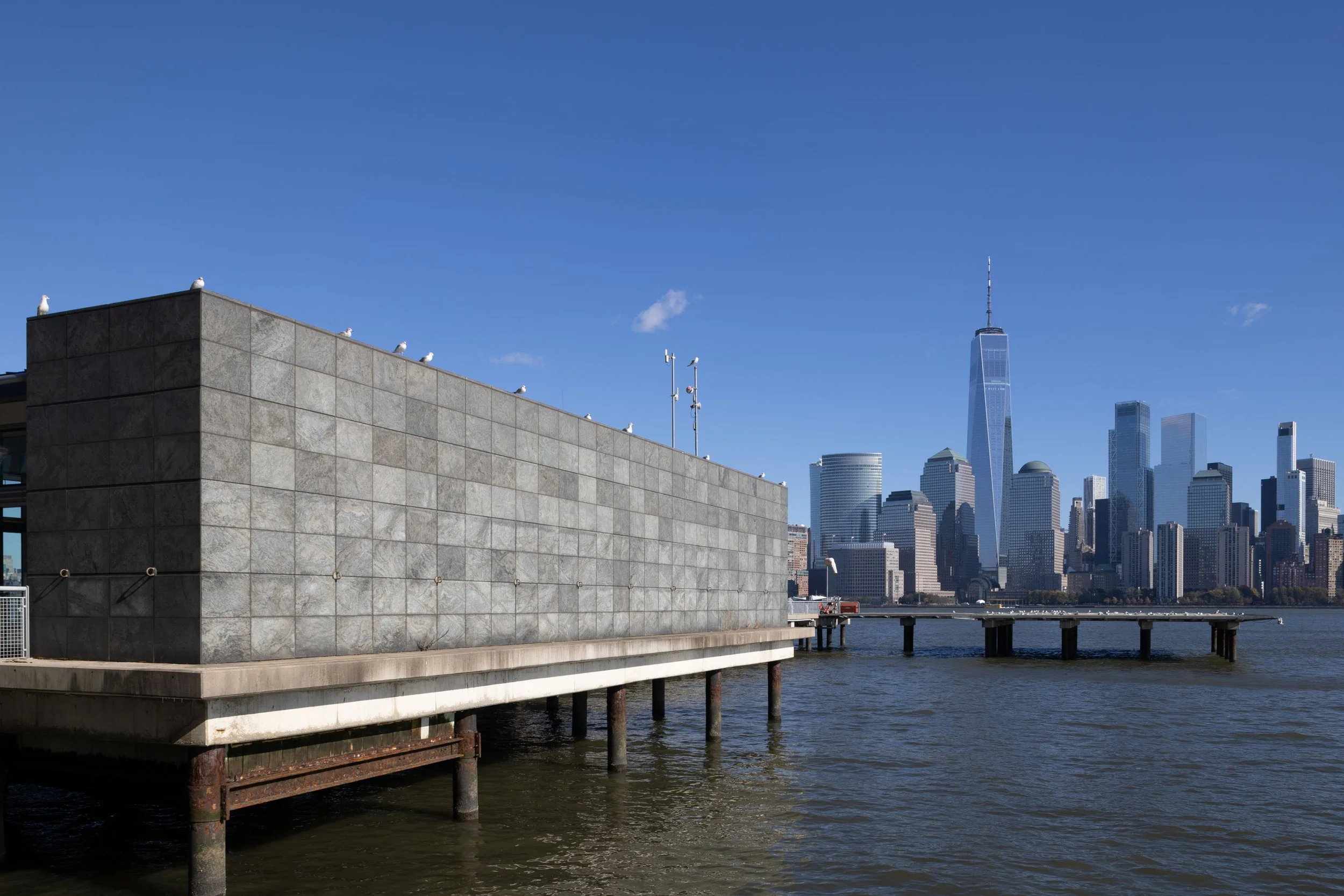
Paulus Hook Ferry Stop, Camera is Level. Vertical edges are vertical in the image
Colgate Clock
In this scene, the viewer tilts their head up significantly to see the whole clock. This causes significant convergence of the vertical lines toward the top of the image. When the camera is leveled, the vertical lines stay parallel. But in order to contain the whole clock, the lens needed to be shifted upward. One way to think of this is the image circle goes with the lens, so shifting the lens up projects a different area of the lens’s image circle onto the sensor. Without shift, a level camera only picks up half the clock at this range. With shift, we see the entire clock and can keep the camera perfectly level to ensure the vertical towers stay parallel. This is a very unnatural looking image because it occurs very far off to the edge of the lens’s field of view. Our eyes have sharpest vision at the center, in the macula. So when we need to see things that are tall, we look up at them. But with a tilt shift lens, we can create unnatural looking images by selecting on the very edge of the image to project onto our sensor.
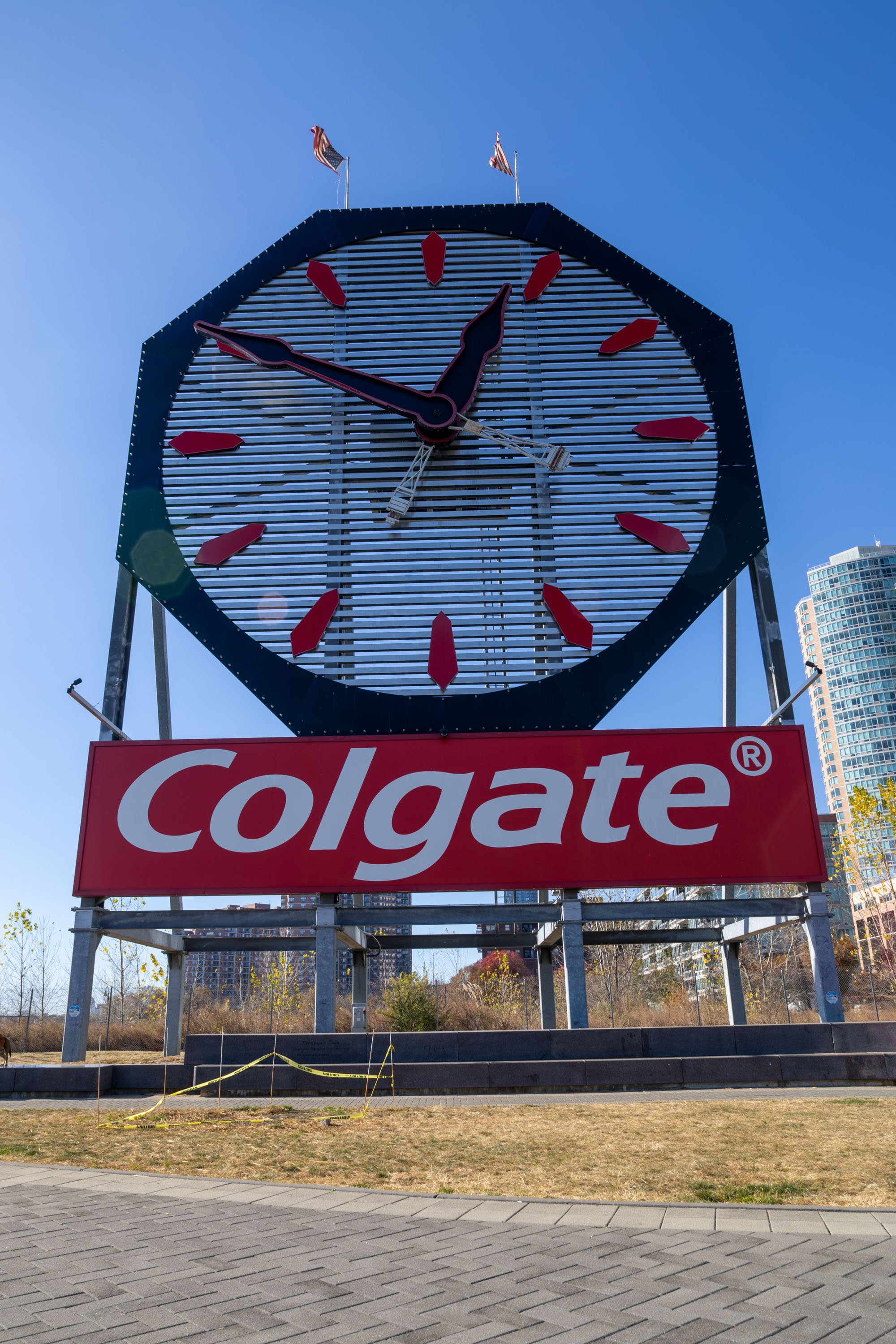
Colgate clock, Jersey City. Natural View.
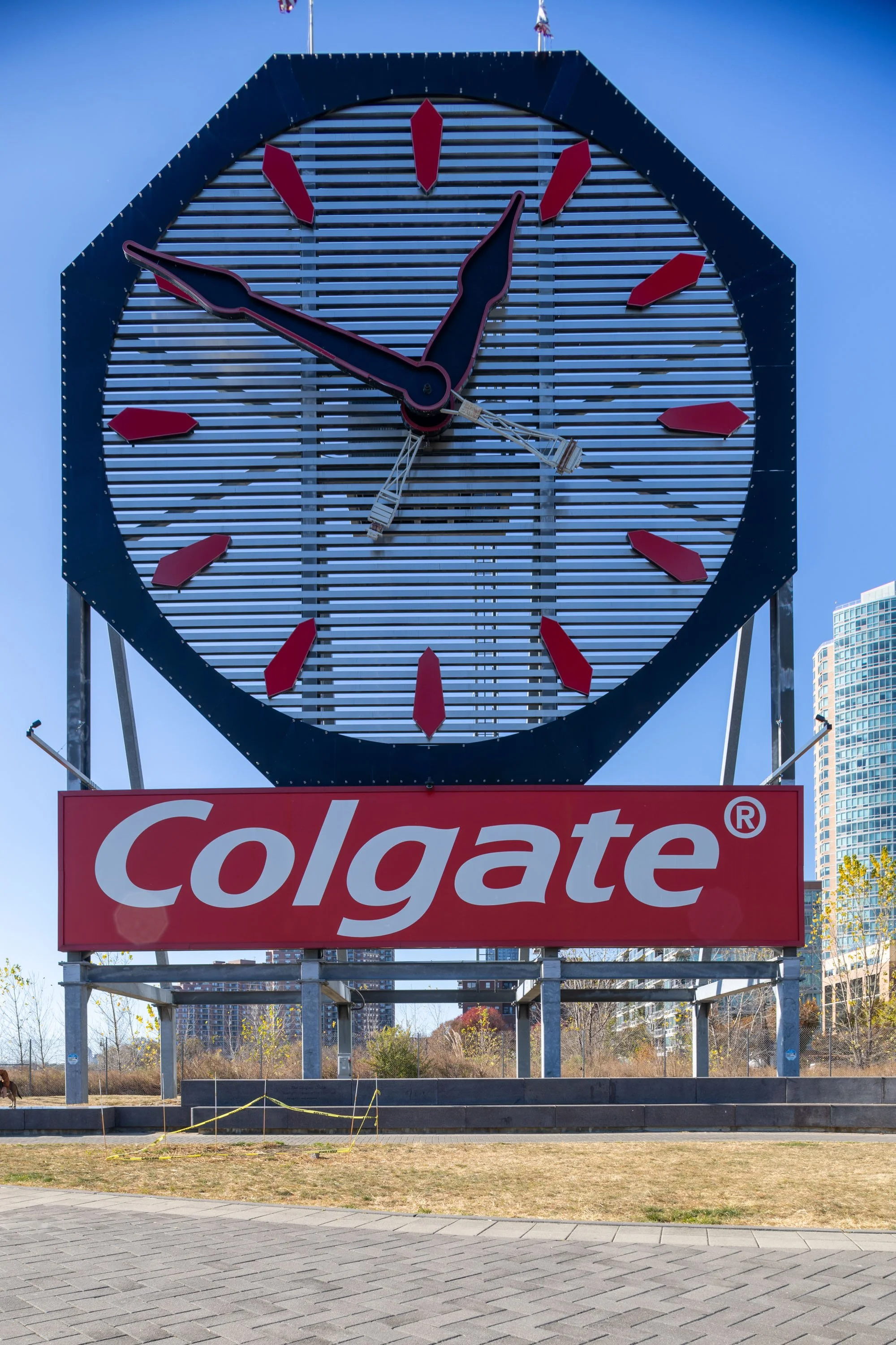
Colgate Clock, Jersey City. Camera leveled, Lens shift used.
So next time you need to ensure the relative sizes of objects in your image is the same, align your camera so that the sensing plane is parallel with the plane of that object. Do this with a geared tripod head and a level. A shifting lens is a good option if you are interested in maximizing the resolution of your perspective controlled shots. But a wide angle lens pointed perfectly level will achieve the same correction. Those images can be cropped to the region of interest. The cropping process is analogous to the shifting the sensor relative to the lens on a shifting lens setup.

Argus A2B Camera - Phoenixville Firebird
Getting a roll of film developed that I shot on an antique Argus A2B camera
For many years now, Phoenixville, PA, around the winter holidays, sets a wooden firebird on fire. My dad took me here in late 2024 to see the yet to be burned firebird. This day I was photographing with my Argus A2B, an inexpensive 1940’s plastic camera made in Ann Arbor, MI. The lens is fixed focus 50mm F/4.5. The focus is fixed at 10 feet, so you need to stop the aperture down a lot to achieve infinity focus. Dad raided his film fridge and donated some Fuji Super HQ 100 ISO film. One interesting feature of the A2B is the completely decoupled lens shuttter and film advance. This makes multiple exposures in the same frame very easy, sometimes too easy. Here is a short youtube video I posted regarding this camera. I made the video before getting the film developed. This blog post shows the results from this roll of Fuji Super HQ 100 ISO film.
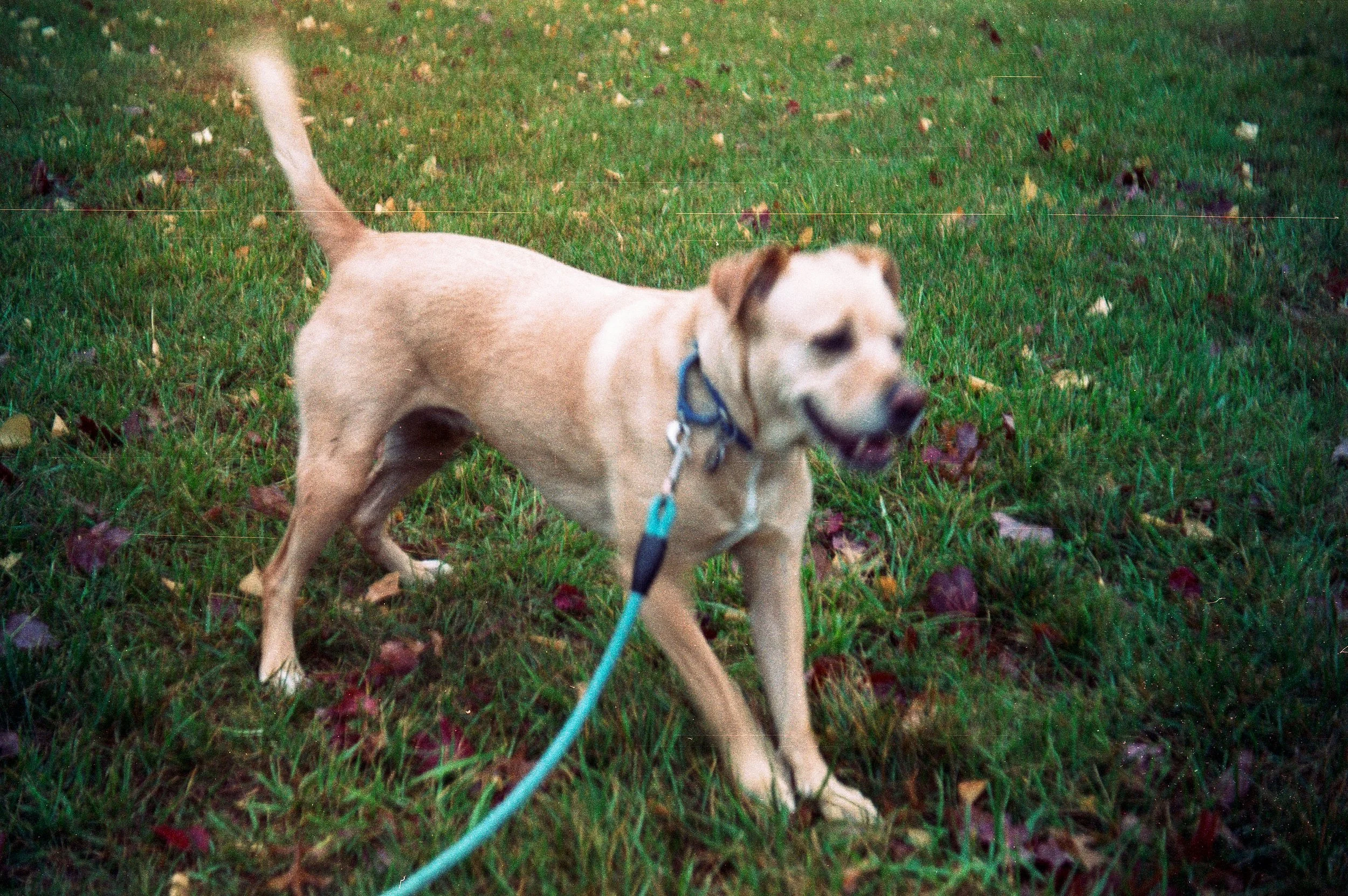
It was cold and rainy on the street I grew up on. I brought the A2B on a dog walk. I asked them if they could pose 10 feet away. I took the shot wide open to see how much blur I can get on the background. I was lucky and got dad and the dog at exactly the right distance for focus. The late autumn maple tree behind him has plenty of background blur. I even see a little ‘swirly bokeh’ people talk about with the Helios 44.

My dad and our dog Sugar. Argus A2B camera. 50mm F/4.5 lens.
Dad and I go places to take photos. In late December, he showed me this place where the firebird was being built. The detail in the wooden design of the head and wings were impressive. A lot of people put work into this structure that will be burned.
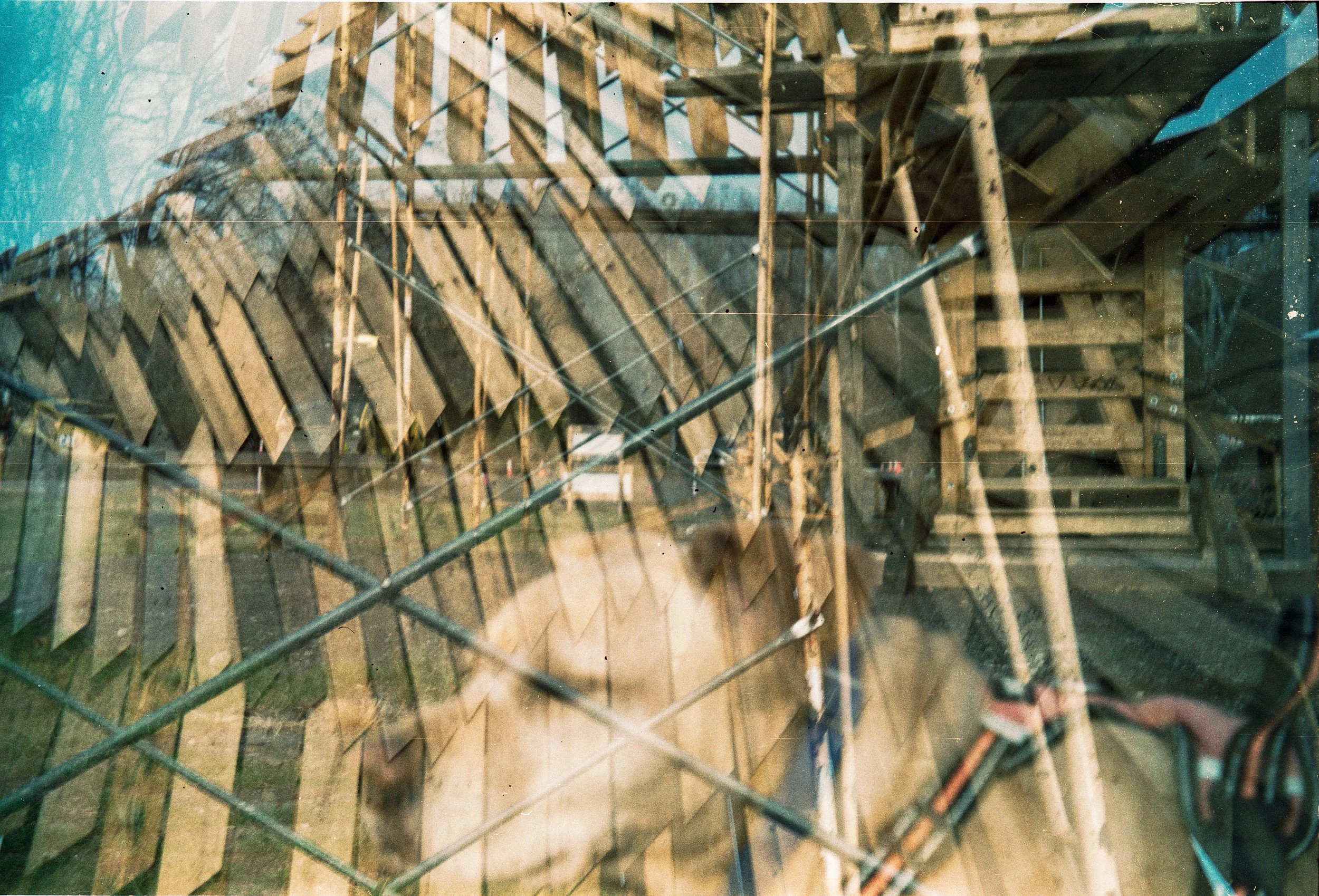
Double exposure of Phoenixville firebird and Sugar the dog
The head of the bird was made of many strips of wood. The beak is carved to look smooth. The wings were being supported by scaffolds.
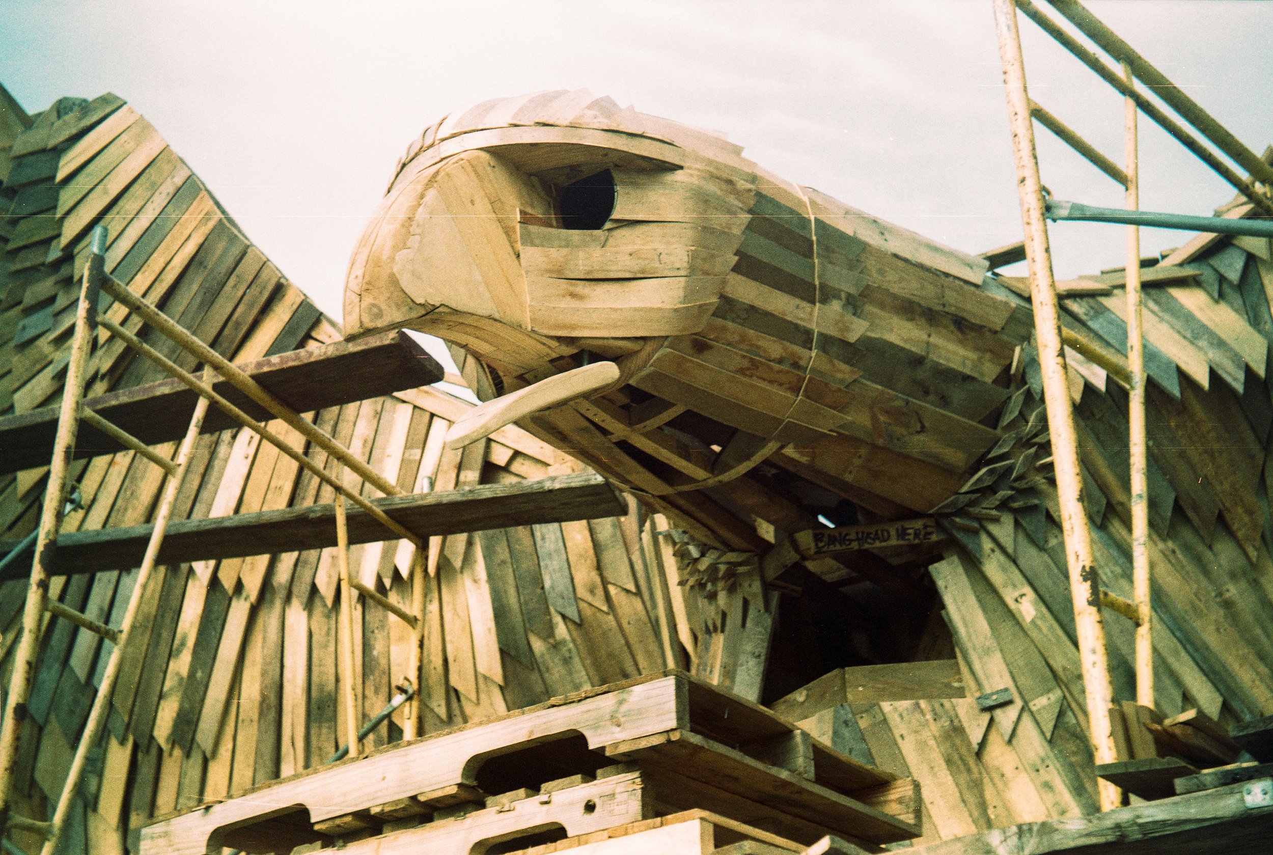
The carved wooden head of the phoenixville firebird
I find the process of taking a double exposure on film to be challenging. Digital cameras have equivalent features that allow you to take one and see it superimposed on the image you are about to capture and overlay. With this camera, you have to remember the areas of the photo that already have detail. I feel that this image is too busy and it’s hard to distinguish the original two images.
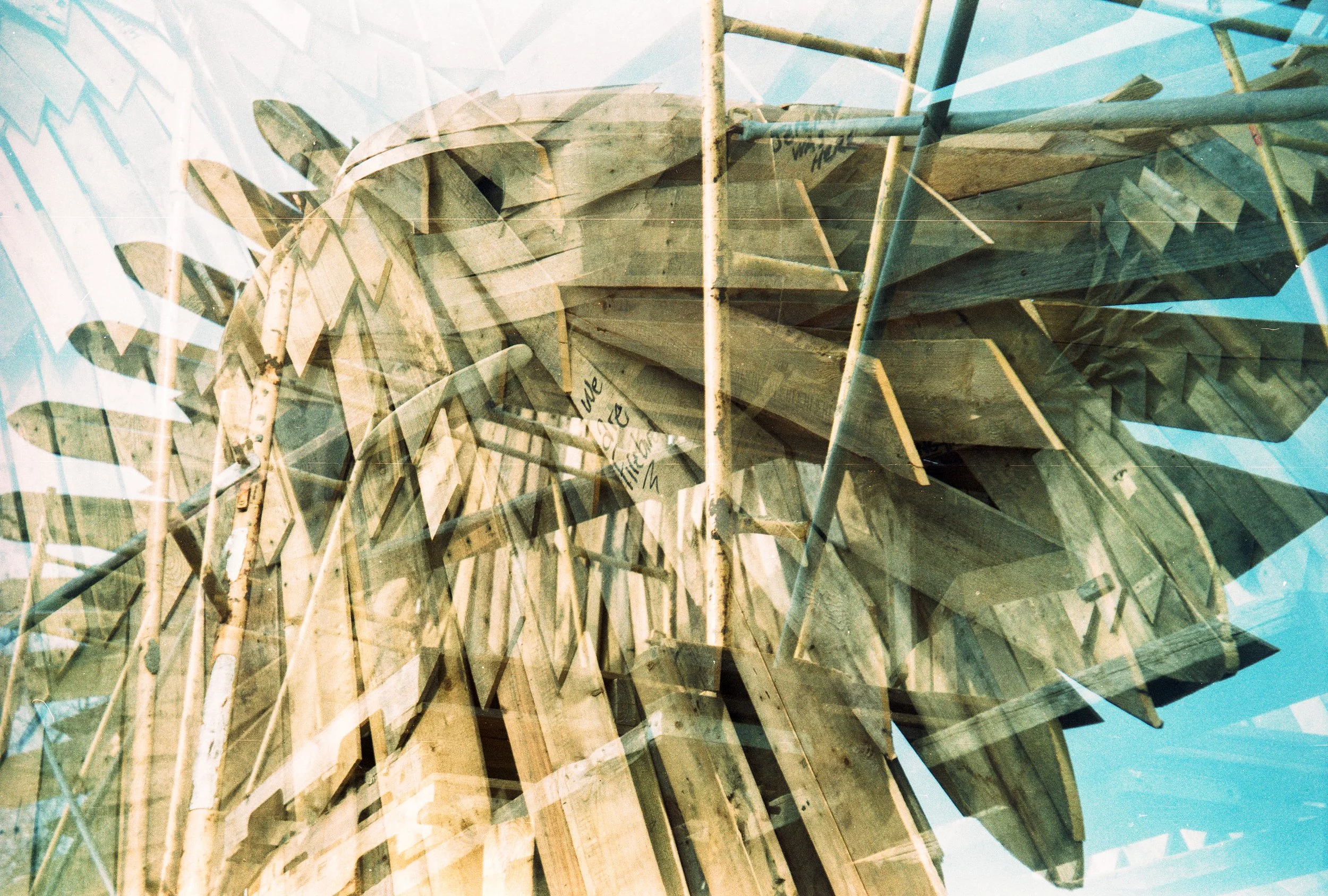
A double exposure of the firebird with wings and head overlayed.
The firebird in this image creates a dark canvas for the image of the dog. The bird is textured with grass. The dog is standing inside the bird.
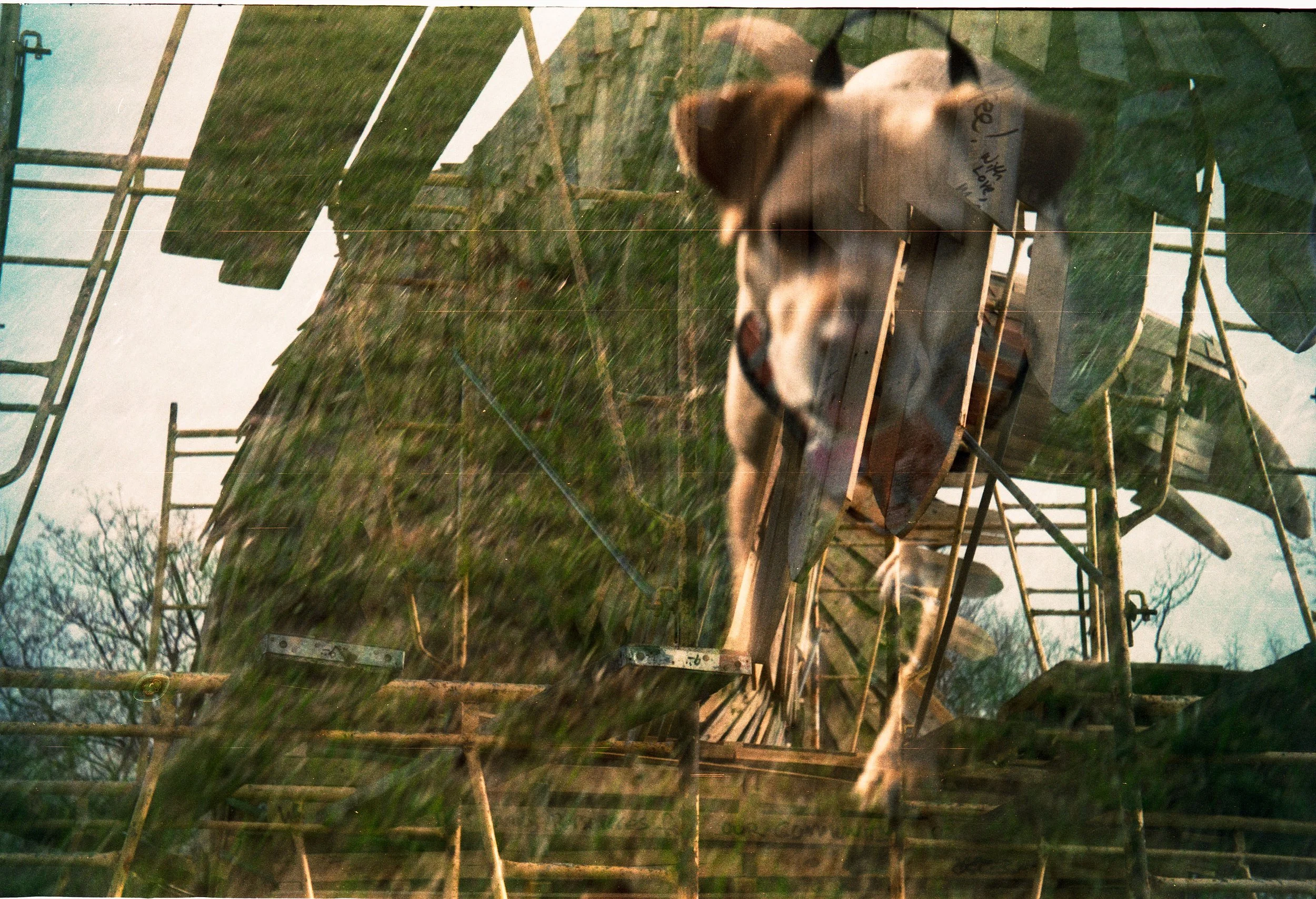
Double exposure of Sugar the dog and the Phoenixville firebird
There must have been a lot of work put into the shape of this beak. The bird which is destined to be burned is being built with a lot of detail.
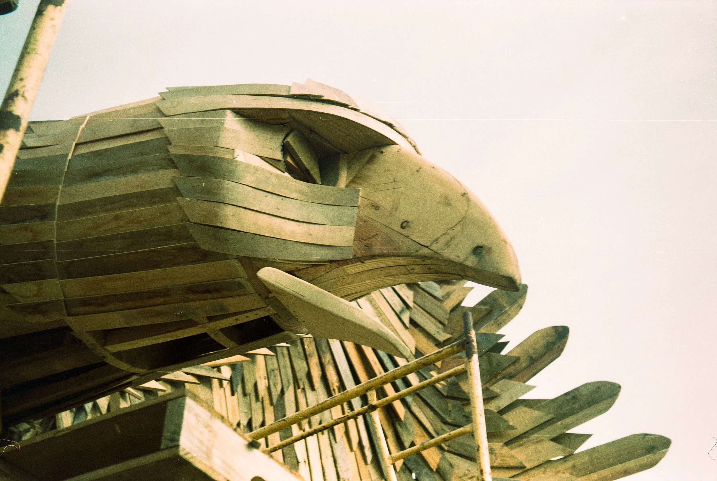
The beautiful carved head of the firebird
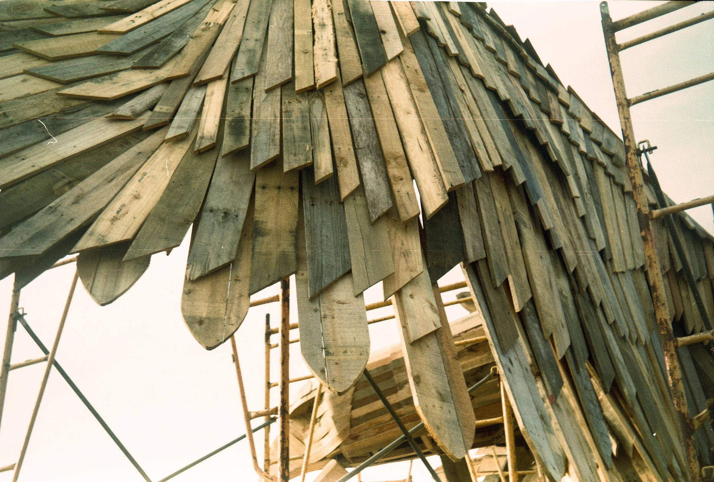
The wing of the firebird with multiple layers of neatly arranged planks.
Sugar the dog.
The camera is easy to use although has a seemingly fragile lens. The shutter release is a small lever sticking out of the side of the lens. You need to remember to unlock the lens from the camera body to put it in proper position for photos. If you forget this step and leave the lens retracted the images will not be in focus. Winding the film is tricky: you must press the advance button and start turning the film winder and let go of the button. A tooth makes the film advance stop at the right position. At the end of the roll, the film will stop when it is all used. It is important to feel the difference between the film advance knob stopping at the tooth or stopping because all the film is used. I made this mistake on my last frame and got a double exposure offset by half a frame.
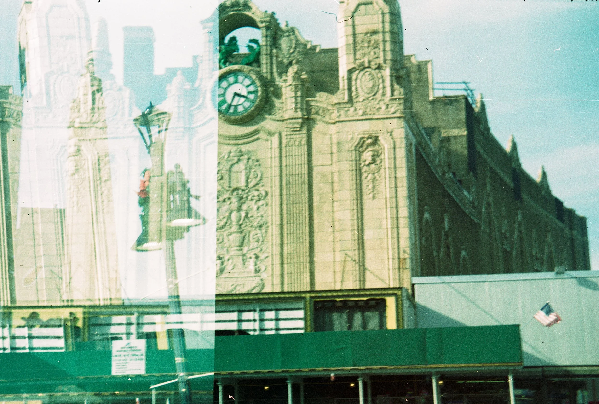
Building in Journal Square, Jersey City. Double exposure, half frame offset. Last exposure of the roll.