Scanner camera
Motivation
I first saw the idea of a scanner camera when I was in college around 2004. I was a camera enthusiast who used the art website Deviant Art, specifically its photography community. I saw a guy in eastern Europe create images from a flat bed scanner and a lens. Digital photography was fairly new at the time and the best cameras had around 6 MP. A flat bed scanner is slow, but has well over 100 MP which was very exciting at the time. But it wasn’t until 2024 that I started to build one of my own. Finally, I would live out my college boyhood dream of building a scanner camera. So, it was my turn to drill into a scanner and convert its purpose to that of a large format camera. What troubles would I run into? Would i be able to make a functional focusing mechanism? How would the images look?
The Lens
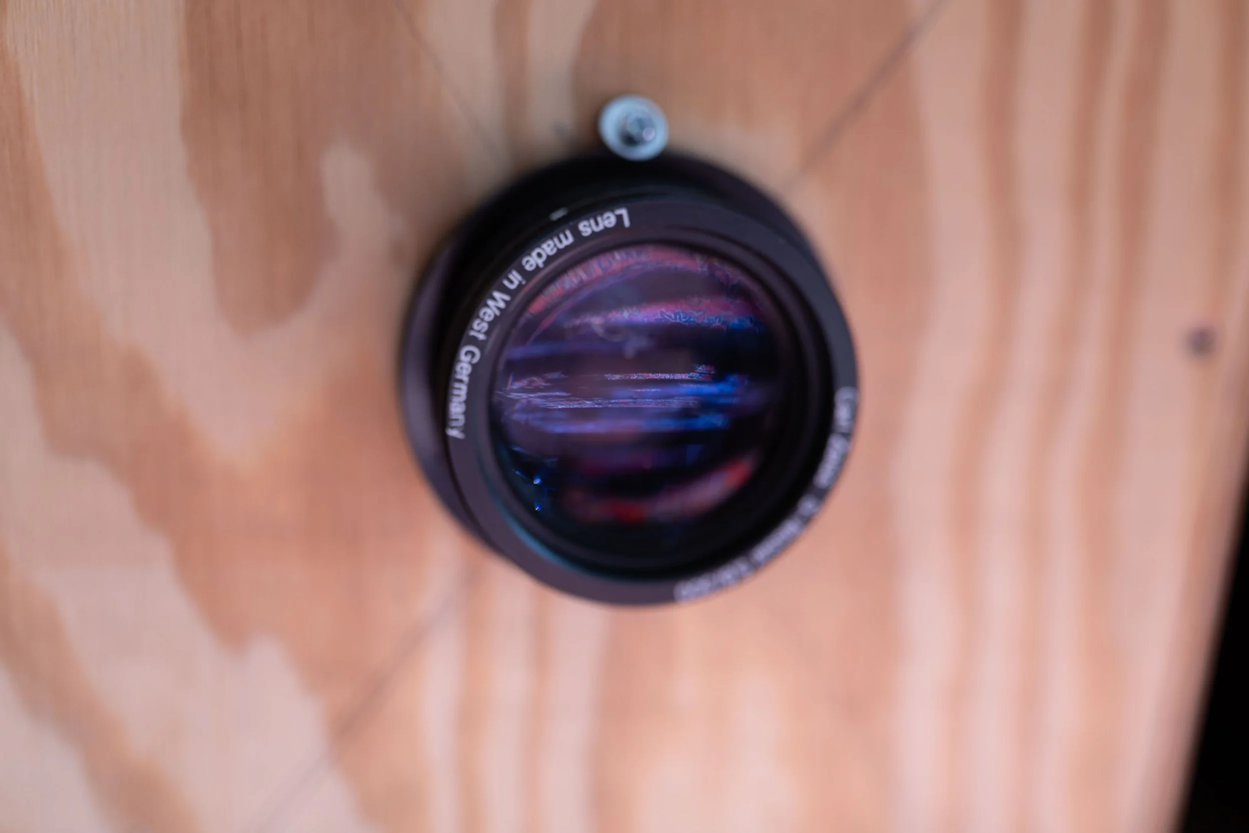
In January 2024, I was spurred to start the scanner cam project when I bought a Carl Zeiss S-Tessar 5,6/300 from ebay. The price of $28 was too good to pass up. This lens has a 300mm focal length. This type of lens is used for large format photography so I was sure it could cover an 8”x10” frame. I bought it with no aperture, so I would only have access to the wide open lens with aperture f/5.6. Now I needed a scanner of about 8”x10'“ scan area.

Carl Zeiss S-Tessar 300mm F/5.6 Large Format Lens
Scanner
I chose a Canon CanoScan LIDE 300. This was the cheapest functioning scanner I could find on ebay. It cost about $35. The scanner is USB powered so I knew I would not need to supply additional DC power. I could power the whole thing from my laptop. As we were taking apart the scanner to try to disable the illumination, we found that it won’t function without the white strip on the back of the glass in place. Because we lacked the ability to hack the scanner to operate without the illumination, we left the illumination turned on. Other scanner camera makers have found ways to disable the illumination so that it doesn’t interfere with picking up the light from the lens.
Camera Design
My design places the lens on the end of a long box with a flatbed scanner at the back. To focus the image, I designed a mechanism to move the scanner farther and closer to the lens. To focus the image at infinity, the scanner is held about 300 mm from the back of the lens. To enable closeup photography, the scanner moves to the back of the box as far as possible. The length of the box, and size of the movement mechanism, dictate the minimum focus distance of the scanner camera.
The movement mechanism was purchased as an adjustable height laboratory stand. My plan was to screw the scanner into one end of the lab stand and connect the bottom of the stand to the back of the box. The knob for adjustment works to adjust focusing distance for the camera.
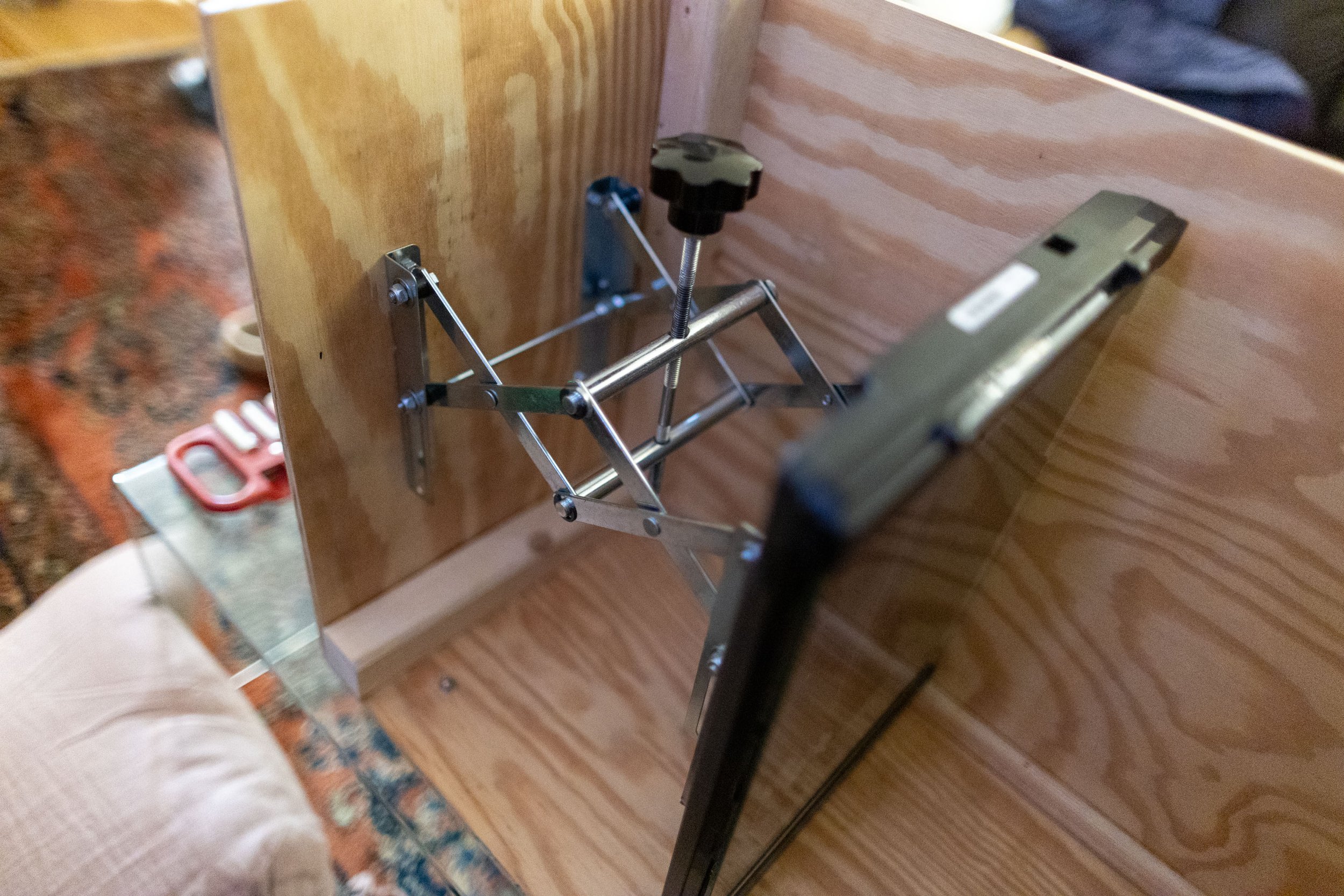
The focusing mechanism inside the wooden camera box. no focusing motor is installed so focus knob adjustment is manual.
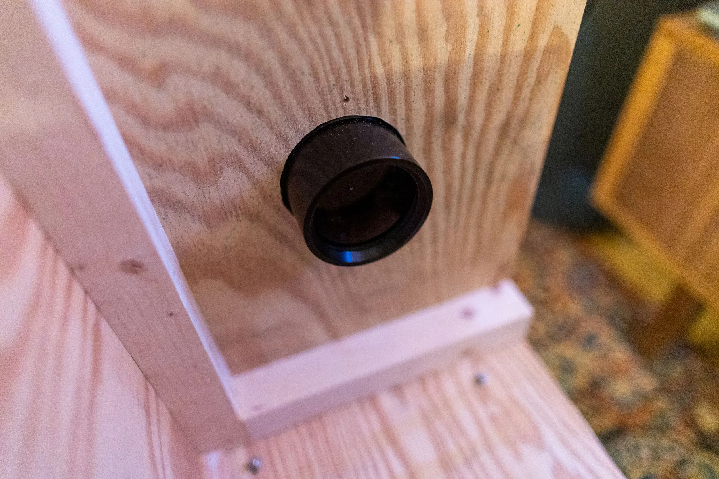
The lens installed the wooden camera box
The backside of the lens installed into the camera box
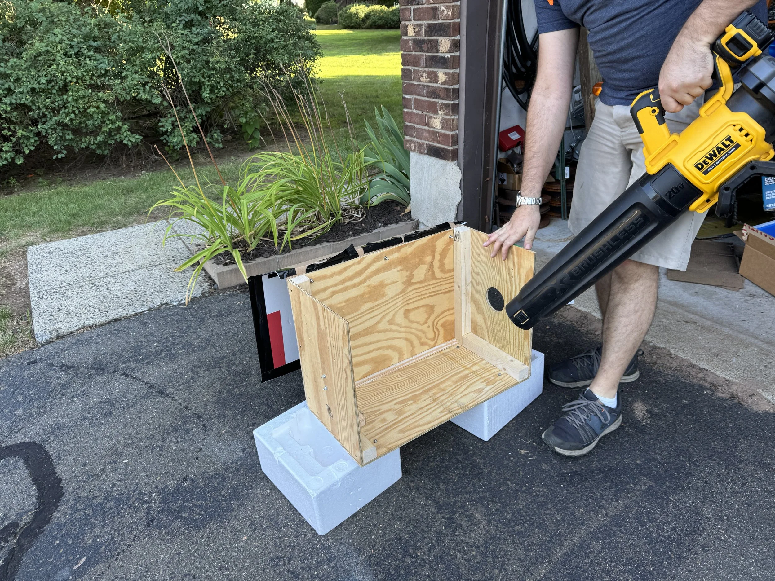
Painting prep on the wooden camera box
Thanks to Steve for the help and use of his shop to build the box. I couldn’t have done it without him.
Camera Usage
Portrait Photography
The lens does not have the usual aperture adjustment present on most lenses. So, diameter of the lens is fixed and the brightness of the image cannot be reduced. If a scene has too much light, the image will be overexposed. In the following image, my parents are illuminated by natural light on a screened in porch, just slightly too bright for the scanner to handle. This resulted in the overexposure in their faces and the background. I really like the vignetting and the weird background texture. The vertical bands inherent to the scan interact with the out of focus porch screen texture to create a unique pattern.

My parents, image from the scanner camera

Closeup of my my mom’s face
Close crop of my dad’s face
Focusing Demonstration
What does the image look like when it’s projected onto the scanner? To answer this question, I hold a pad of paper onto the scanner bed. Partially closing the lid blocks most outside light still allowing me to point my video camera inside. As I rack the focus from infinity to macro, you can see the focus go from the buildings outside my window to the plants in front of my window. As expected, the image is inverted and the buildings are at the top of the image.
Calculating Maximum Magnification
To focus at something infinitely far away, move the scanner bed to about 300 mm from the lens (the focal length). To focus closer, move the scanner to toward the back of the box. When the scanner is in the back of the box, the scan bed is about 445 mm from the lens plane. The lens focal length is 300 mm. Using the Gauss thin lens equation, the focusing distance will be 920 mm from the lens. F = 300 and S’ = 445, so S = 920. This means that the maximum magnification produced by this camera is .48:1 (m = 445 / 920 = .48), or approximately 1:2. This means that when camera is set to minimum focusing distance, the image is about half the size of the object being photographed.
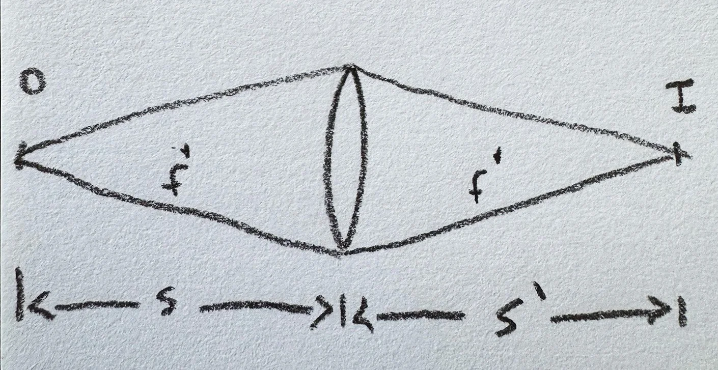
Diagram of a lens forming and image of an object with distances s, s’ labeled.

Gauss thin lens equation
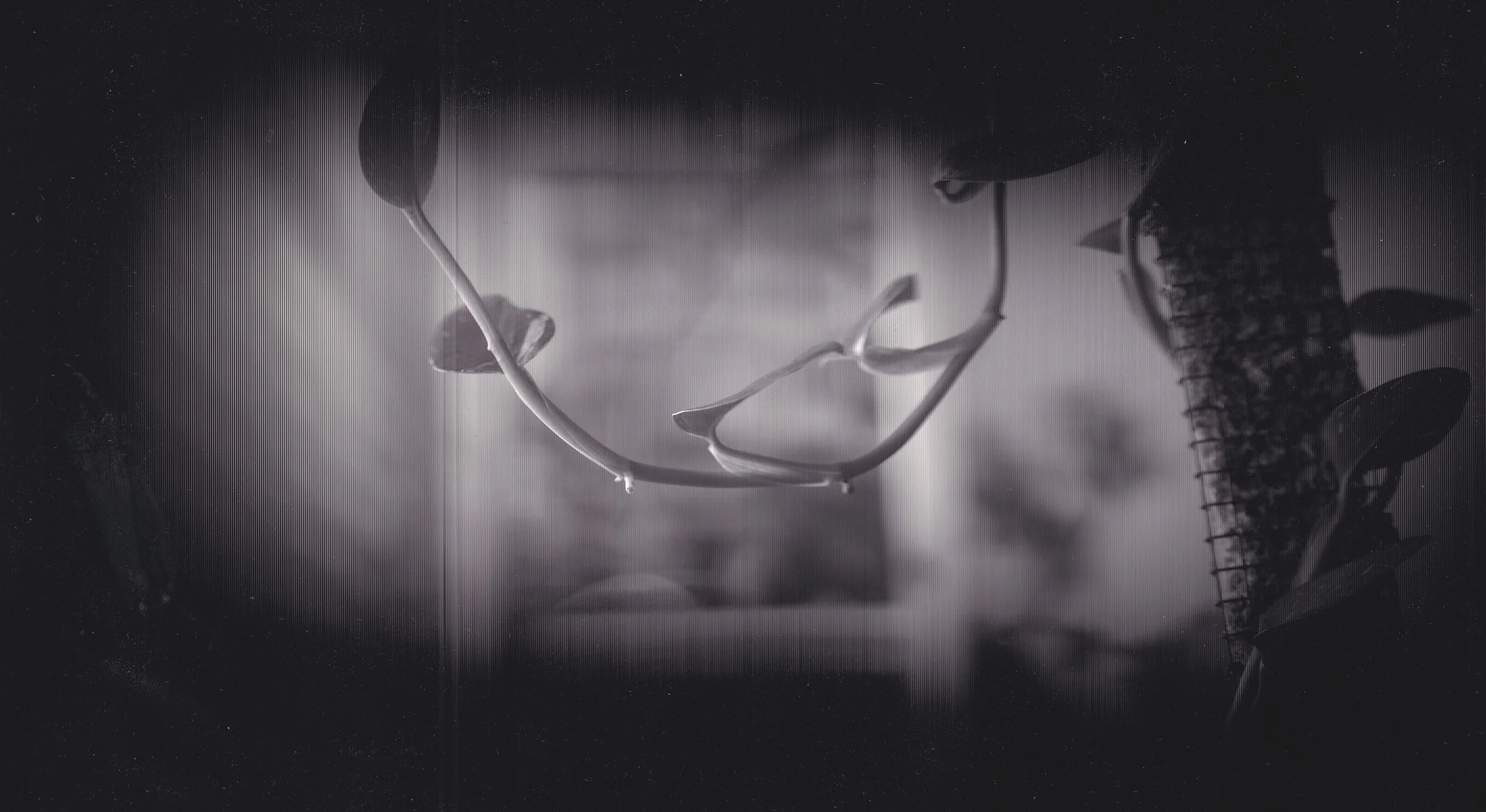
Closeup photography
In this image, I photographed a succulent plant Crassula Ovata “Gollum”. It is putting out a new pair of leaves above the lowermost leaf on the left. The trunk is starting to turn from green to a calloused brown. The image shows the new leaves in clear focus and the texture of the trunk is visible. There is pleasing blur on the edges of the pots that are not in the plane of focus.
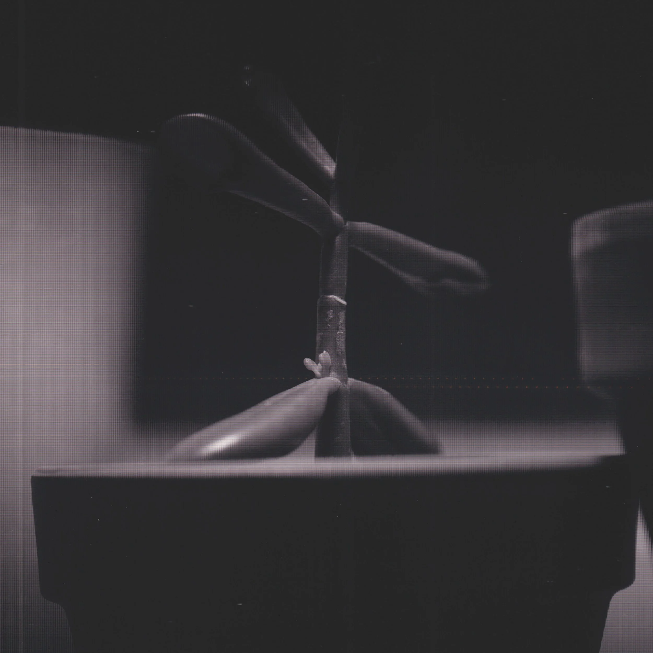
Crassula Ovata Gollum. Closeup photo with the scanner camera
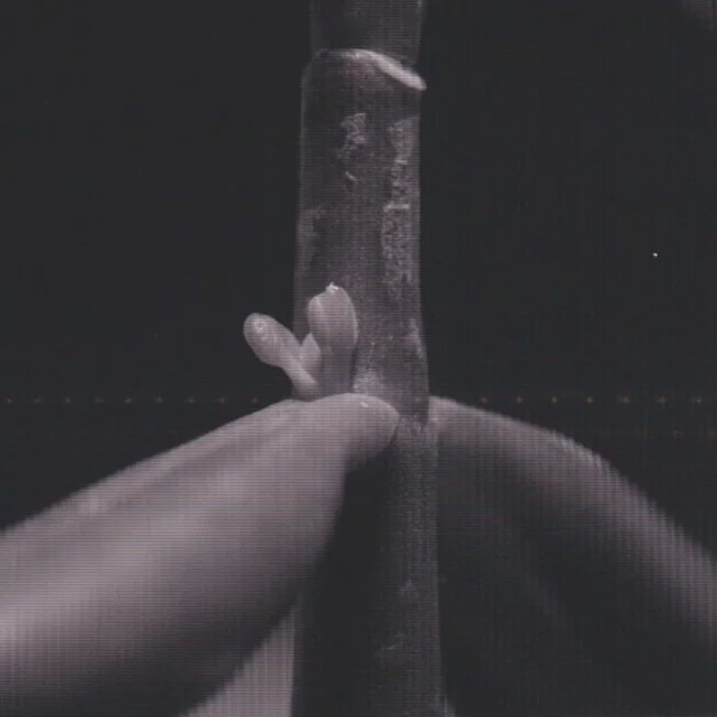
Closeup of the new leaves, 100% crop
Vignetting
One problem with the camera is that most of the image area is black. Visually, you can see the image projected over the entire scanner bed with a piece of paper taped on, as shown in the video before. Therefore, the lens is providing an image over the whole scan area. The likely reason for the vignetted images is the angle of the light from the lens as it enters the scanner. Light near the middle is entering nearly perpendicular to the scanner. While light reaching the edge of the scanner comes in at an angle, not perpendicular. My guess is that the sensor in the scanner is made to be insensitive to off angle light. This would keep the scanner focused on a small area of a document. But as a camera, this is not ideal.
monstera standelyana vine hanging down. photo taken with scanner cam.
Some people have suggested using a fresnel lens on the scan bed to refract the light into the axial direction, the direction that the scanner should be most sensitive to. I have not obtained an A4 size fresnel lens, so the best images I have capture thus far have been highly vignetted. The following image is the full width of the scanner (about 8 inches) and is cropped in the vertical dimension from about 11 inches down
Focusing Motor
I wanted to be able to focus the scanning bed without manually adjusting the focus knob. I wanted a switch to activate a motor to drive the focus mechanism. So I designed a DC circuit that powers a motor for this purpose.
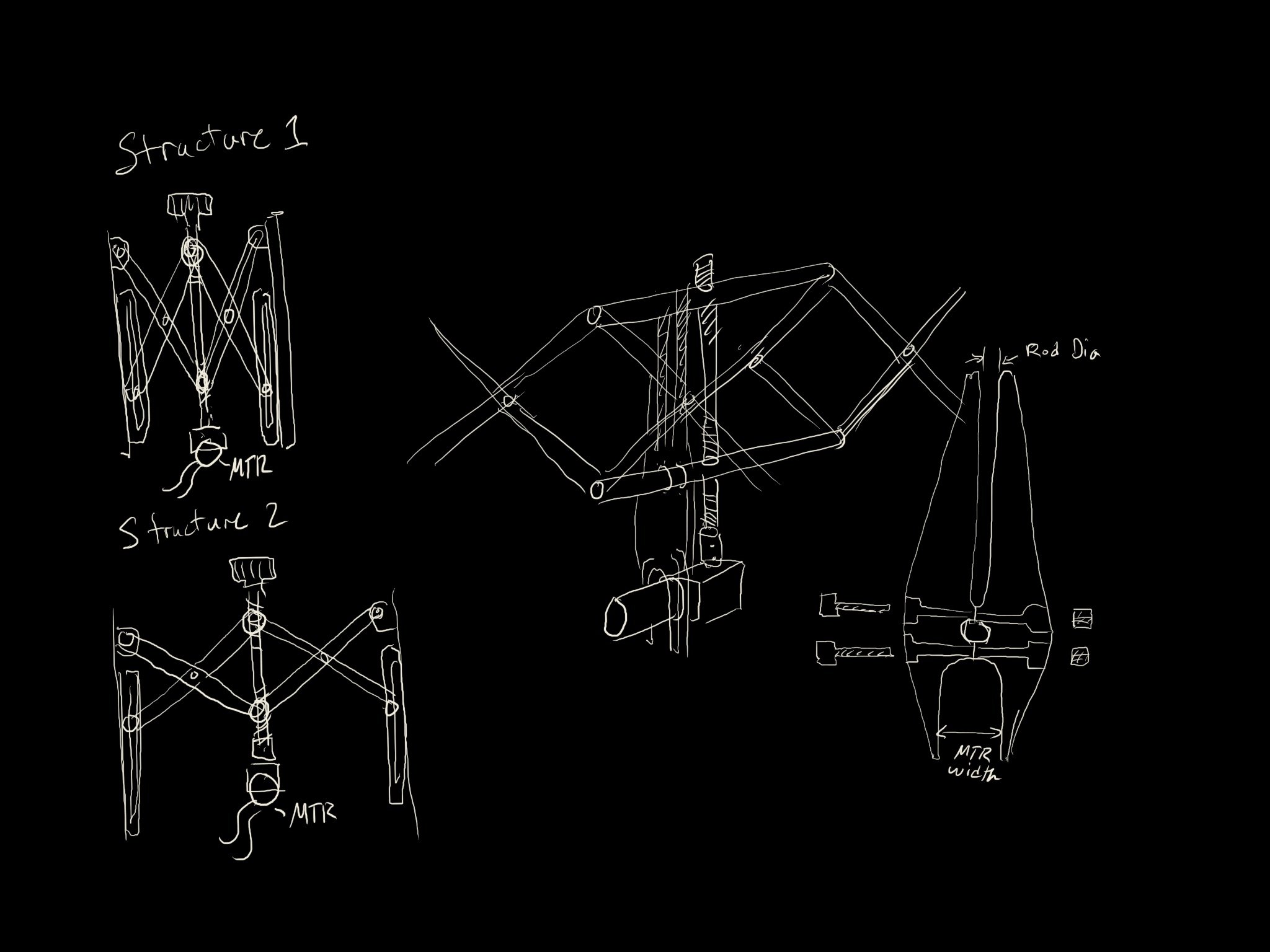
Drawings of a motorization design for the scanner movement mechanism
The stabilizing frame that reacts the motor torque into the upper bar of the lifting assembly is made of plywood. We initially tried 3D printing this piece but ran into technical difficulties in the print. So we switched the design to plywood to make it work. This piece is required to prevent the gear motor from spinning around in the box when the voltage is applied. The switch on the back of the box is a double pole double throw switch (DPDT). This type of switch allows me to reverse the polarity of the voltage on the motor, enabling adjustment in both directions. When the scanner is near the middle of the box, focus is at infinity. when the scanner is at the back of the box, focus is closeup.
Cost
The project was completed in two phases. Phase 1: creating the box with lens, scanner, and focusing assembly was completed in Q1 of 2024. Phase 2: building the DC circuit and focusing motor assembly, installing motor and control assembly, installing brass handles, was completed in Q3 of 2024. The total cost for components was about $163. The price of this lens seems to be a bit higher now. I would recommend a different scanner. Try to find one with a RGB sensor so that the images from the scan will have color information. This type of scanner has a monochromatic sensor and pulses RGB lights at the document to resolve color information. This type of sensor cannot resolve color information from continuous light sources. This might mean choosing a very old scanner. One that might have been available in 2004 when the original scanner camera was built. Also, 3D printed housings might be a better choice than plywood, which is heavy and expensive.
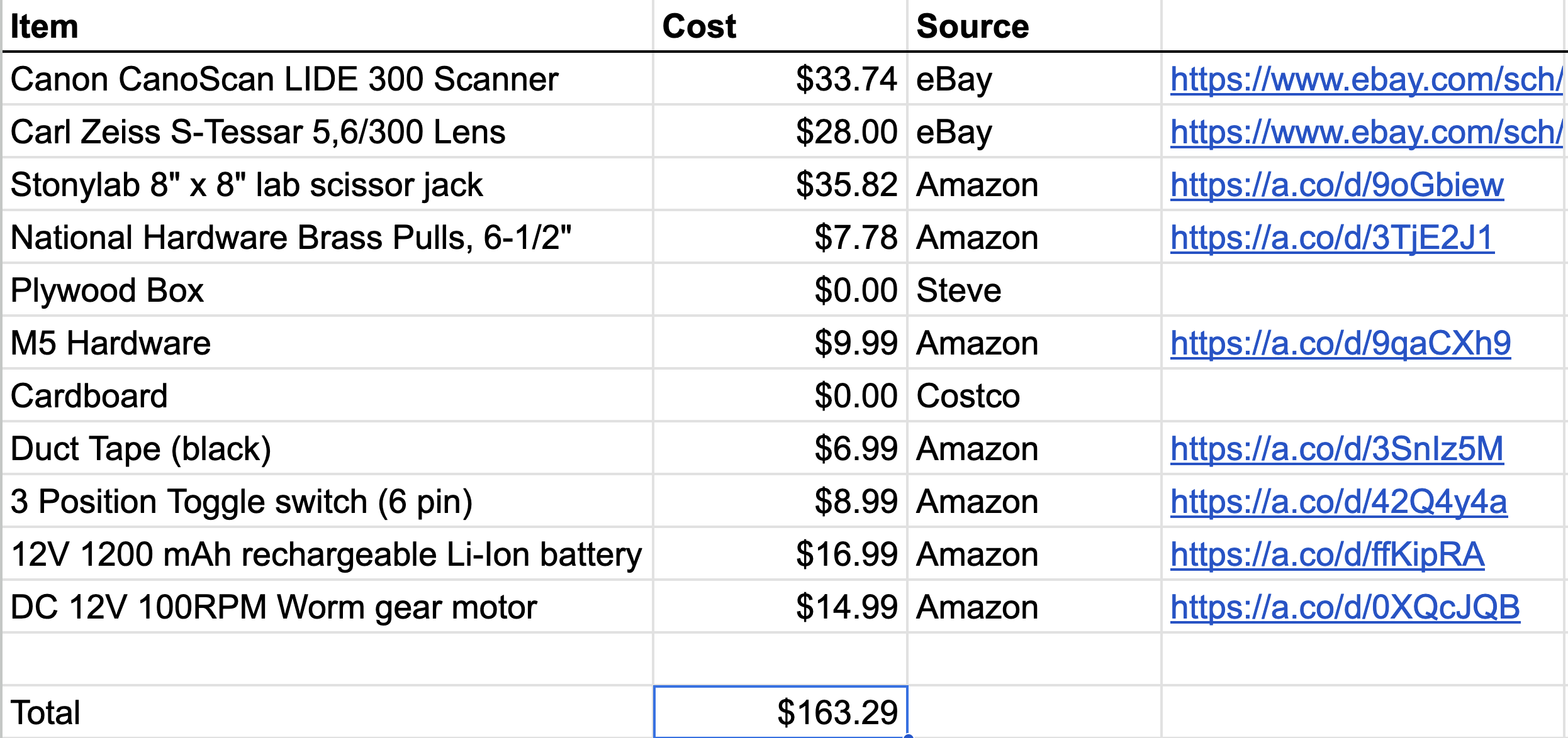
Bill of Material for the scanner camera build
Thanks Steve
Steve and I started our aerospace engineering careers around the same time. We have been friends for many years. We used his basement shop to build the box for the camera. Thanks Steve!
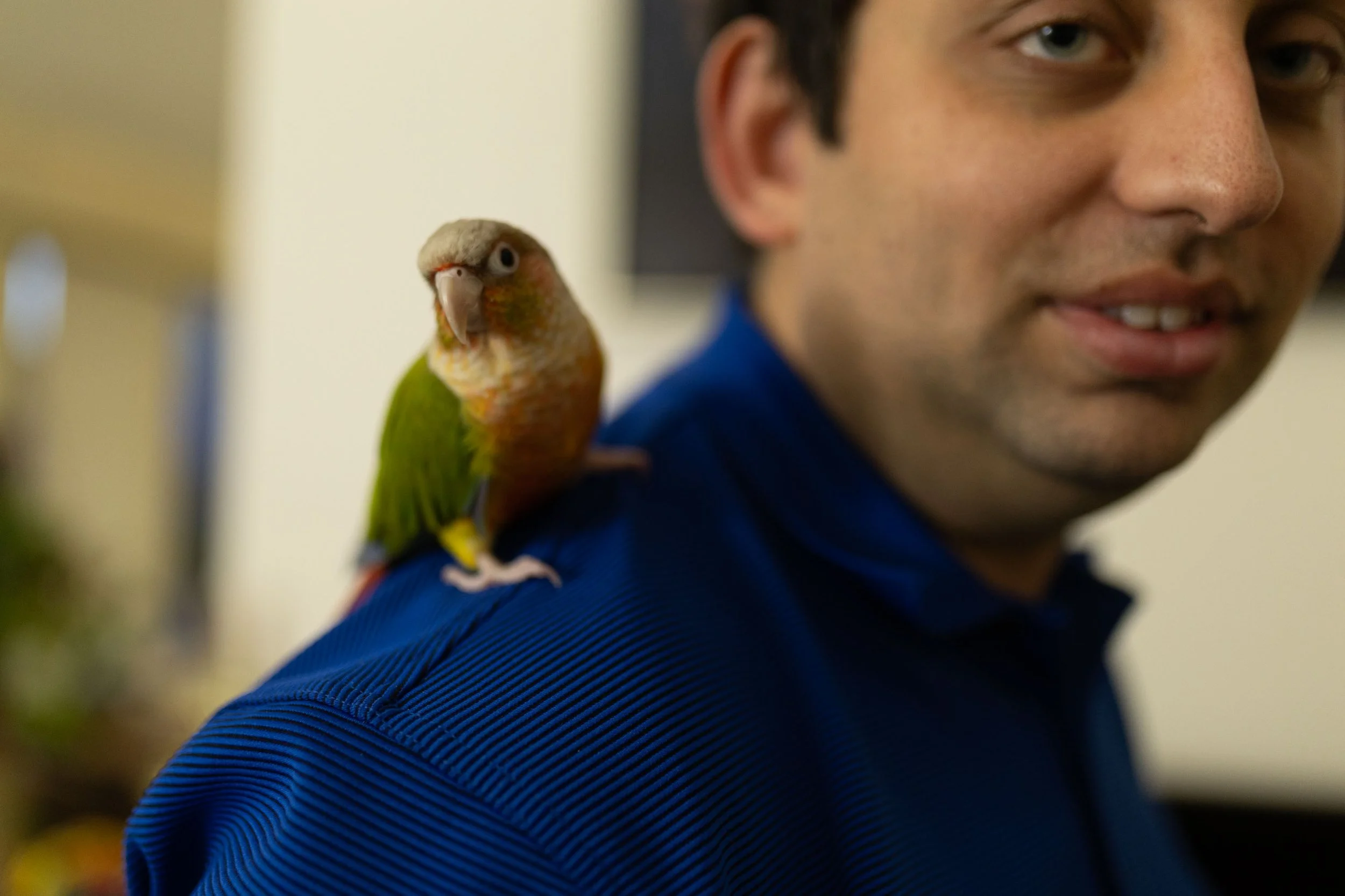
Steve and Chirp